Service Manual
Page 7
...50 Hz/60 Hz, Output: 15.6 V DC, 8.0 A 1-1 CF-74CCBAXBM / CF-74CCBADBM CPU Intel® Core™ Duo Processor T2400 (1.83 GHz, 2 MB*1 L2 cache, 667 MHz FSB) Chipset Intel® 945GM Memory*1 512 MB (1536 MB Max.) Video Memory*1*2 UMA (128 MB Max.) Hard Disk Drive*3 Approx. 80 GB ...and select [Information] menu. [CPU Speed]: CPU speed, [System Memory]: Memory size, [Hard Disk]: Hard disk drive size Main Specifications Model No. Specifications This page provides the specifications for the basic model CF-74CCBAXBM/CF-74CCBADBM. To check the model number: Check the bottom of the...
...50 Hz/60 Hz, Output: 15.6 V DC, 8.0 A 1-1 CF-74CCBAXBM / CF-74CCBADBM CPU Intel® Core™ Duo Processor T2400 (1.83 GHz, 2 MB*1 L2 cache, 667 MHz FSB) Chipset Intel® 945GM Memory*1 512 MB (1536 MB Max.) Video Memory*1*2 UMA (128 MB Max.) Hard Disk Drive*3 Approx. 80 GB ...and select [Information] menu. [CPU Speed]: CPU speed, [System Memory]: Memory size, [Hard Disk]: Hard disk drive size Main Specifications Model No. Specifications This page provides the specifications for the basic model CF-74CCBAXBM/CF-74CCBADBM. To check the model number: Check the bottom of the...

Service Manual
Page 8
...GHz *1 1MB = 1,048,576 bytes *2 A segment of "Trusted Platform Module (TPM)". *14 This slot does not support the MultiMedia card. Minimum) *21 Measured using the dithering function. *10 Maximum resolution depends on the specifications of the external display. *11 Only for model with wireless LAN *12 Only for Panasonic SD Memory... is OFF. Your operating system or some application software will report as fewer GB. *4 The data transfer rate of the Video Memory cannot be used. *9 A 16,777,216 color display is allotted automatically depending on the computer's operating status. The size of...
...GHz *1 1MB = 1,048,576 bytes *2 A segment of "Trusted Platform Module (TPM)". *14 This slot does not support the MultiMedia card. Minimum) *21 Measured using the dithering function. *10 Maximum resolution depends on the specifications of the external display. *11 Only for model with wireless LAN *12 Only for Panasonic SD Memory... is OFF. Your operating system or some application software will report as fewer GB. *4 The data transfer rate of the Video Memory cannot be used. *9 A 16,777,216 color display is allotted automatically depending on the computer's operating status. The size of...
Service Manual
Page 10
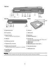
P : Battery pack Q :Battery latch R :Multimedia pocket release button G :SD Memory Card indicator (Blinking: During access or a password is requested) H :Ventilation hole I : Stylus holder J : DC-IN jack S : Hard disk drive latch T : RAM module slot...EX PC Bottom A :ExpressCard slot K :LAN port B :PC Card slot L : Modem port C :Smart Card slot M :Serial port N :External display port D :USB port E : SD Memory Card slot F : Expansion bus connector O :Security lock You can connect a Kensington cable. Refer to the instruction manual of the cable. Select a position with a thick cloth...
P : Battery pack Q :Battery latch R :Multimedia pocket release button G :SD Memory Card indicator (Blinking: During access or a password is requested) H :Ventilation hole I : Stylus holder J : DC-IN jack S : Hard disk drive latch T : RAM module slot...EX PC Bottom A :ExpressCard slot K :LAN port B :PC Card slot L : Modem port C :Smart Card slot M :Serial port N :External display port D :USB port E : SD Memory Card slot F : Expansion bus connector O :Security lock You can connect a Kensington cable. Refer to the instruction manual of the cable. Select a position with a thick cloth...

Service Manual
Page 11
... Bridge Ethernet GBe Yukon Ultra Marvell MiniCard PCI Express Bus Express Card GBE antenna Wireless LAN Golan 11ABG PM Signals SO-DIMM Main Memory DDR2 SDRAM SO-DIMM Extension Memory DDR2 SDRAM 3.3V 32bit PCI Bus 33MHz PCMCIA R5C811A/812A SD Card Smart Card TYPE II RJ11 Data Modem Agere or Conexant...
... Bridge Ethernet GBe Yukon Ultra Marvell MiniCard PCI Express Bus Express Card GBE antenna Wireless LAN Golan 11ABG PM Signals SO-DIMM Main Memory DDR2 SDRAM SO-DIMM Extension Memory DDR2 SDRAM 3.3V 32bit PCI Bus 33MHz PCMCIA R5C811A/812A SD Card Smart Card TYPE II RJ11 Data Modem Agere or Conexant...
Service Manual
Page 14
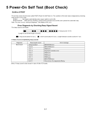
... checking beep sound or error code. 5 Power-On Self Test (Boot Check) Outline of POST The set is placed into automatic stop. z Normal finish .....After memory checking, a beep sound is issued once and the set has a boot check function called POST (Power-On Self Test) in case of sound.) (1 (long sound...
... checking beep sound or error code. 5 Power-On Self Test (Boot Check) Outline of POST The set is placed into automatic stop. z Normal finish .....After memory checking, a beep sound is issued once and the set has a boot check function called POST (Power-On Self Test) in case of sound.) (1 (long sound...
Service Manual
Page 15
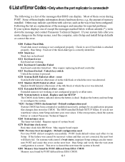
...0212 Keyboard Controller Failed Keyboard controller failed test. Replace and run Setup. If the error persists, check the system battery or contact Panasonic Technical Support. 0260 System timer error The timer test failed. On systems with control of the 64k block at which the error ... require board repair. *0280 Previous boot incomplete - If the failure was detected. 0232 Extended RAM Failed at offset : nnnn Extended memory not working or not configured properly at offset nnnn of wait states, improper Setup settings can display. Following the list are not corrected...
...0212 Keyboard Controller Failed Keyboard controller failed test. Replace and run Setup. If the error persists, check the system battery or contact Panasonic Technical Support. 0260 System timer error The timer test failed. On systems with control of the 64k block at which the error ... require board repair. *0280 Previous boot incomplete - If the failure was detected. 0232 Extended RAM Failed at offset : nnnn Extended memory not working or not configured properly at offset nnnn of wait states, improper Setup settings can display. Following the list are not corrected...
Service Manual
Page 16
...Write down and follow the information shown on the screen. Cache disabled Contact Panasonic Technical Support. 02F0: CPU ID: CPU socket number for offset address of the bits at the RAM address which failed the memory test. device address Conflict Address conflict for checking errors in System, Extended... or Shadow memory. If it cannot locate the address, it displays ????. Press to start the boot process or...
...Write down and follow the information shown on the screen. Cache disabled Contact Panasonic Technical Support. 02F0: CPU ID: CPU socket number for offset address of the bits at the RAM address which failed the memory test. device address Conflict Address conflict for checking errors in System, Extended... or Shadow memory. If it cannot locate the address, it displays ????. Press to start the boot process or...
Service Manual
Page 19
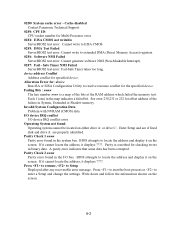
... From the menu screen shown below . 1 SPEAKER TEST 2 VESA MODE TEST 3 CPU 4 (CPU related) A20 GATE TEST CACHE ON/OFF TEST 5 NPU OPERAND TEST 6 RAM (Memory related) RAM STANDARD TEST 7 CONTROL DMA PAGE REG TEST 8 (Control ICs on FD 1. HDD read Test 3. Modem I /F test 5. Quit Select please [ 1, 2, 3, 4, 5, 6, Q ] ? 8.1.1 List of main test... R/W test Extension CMOS R/W test Test function settings Test condition save/play Test automatic execute Error display (Paging style) Following file command Test executed on FD (CF-74) 2.
... From the menu screen shown below . 1 SPEAKER TEST 2 VESA MODE TEST 3 CPU 4 (CPU related) A20 GATE TEST CACHE ON/OFF TEST 5 NPU OPERAND TEST 6 RAM (Memory related) RAM STANDARD TEST 7 CONTROL DMA PAGE REG TEST 8 (Control ICs on FD 1. HDD read Test 3. Modem I /F test 5. Quit Select please [ 1, 2, 3, 4, 5, 6, Q ] ? 8.1.1 List of main test... R/W test Extension CMOS R/W test Test function settings Test condition save/play Test automatic execute Error display (Paging style) Following file command Test executed on FD (CF-74) 2.

Service Manual
Page 23
... GATE TEST 2 (CPU related) CACHE ON/OFF 3 NPU OPERAND TEST 4 RAM (Memory related) RAM STANDARD 5 CONTROL DMA PAGE REG TEST 6 (Control ICs on /off Floating point processor function Memory standard DMA page register DAM register DAM transfer test Interrupt controller Interrupt controller Real time clock...write/read/write protection Only HDD lead selected Parallel port Parallel port Extension CMOS R/W test 8-6 CMOS R/W TEST Contents Address 20 line Cache memory on the DMA REGISTER TEST 7 main board, etc.) DMAC Transfer TEST 8 PIC HALT INSTRUCTION TEST 9 PIC REGISTER TEST 10 RTC ...
... GATE TEST 2 (CPU related) CACHE ON/OFF 3 NPU OPERAND TEST 4 RAM (Memory related) RAM STANDARD 5 CONTROL DMA PAGE REG TEST 6 (Control ICs on /off Floating point processor function Memory standard DMA page register DAM register DAM transfer test Interrupt controller Interrupt controller Real time clock...write/read/write protection Only HDD lead selected Parallel port Parallel port Extension CMOS R/W test 8-6 CMOS R/W TEST Contents Address 20 line Cache memory on the DMA REGISTER TEST 7 main board, etc.) DMAC Transfer TEST 8 PIC HALT INSTRUCTION TEST 9 PIC REGISTER TEST 10 RTC ...

Service Manual
Page 24
... PCB PORT REPLICATOR CN6 CN7 CN24 CN12 CN19 CN14 LAN JACK MODEM MODEM JACK USB CN16 ANTENNA PCB L CN28 MAIN PCB CN5 CN25 CN4 DIMM MEMORY CARD CN8 CN2 CN3 SPEAKER (L) CN1002 USB PCB CN1701 USB CN1702 DC-IN JK1501 CN1501 DC-IN PCB DVD-ROM DRIVE FAN MOTOR LITHIUM BATTERY...
... PCB PORT REPLICATOR CN6 CN7 CN24 CN12 CN19 CN14 LAN JACK MODEM MODEM JACK USB CN16 ANTENNA PCB L CN28 MAIN PCB CN5 CN25 CN4 DIMM MEMORY CARD CN8 CN2 CN3 SPEAKER (L) CN1002 USB PCB CN1701 USB CN1702 DC-IN JK1501 CN1501 DC-IN PCB DVD-ROM DRIVE FAN MOTOR LITHIUM BATTERY...

Service Manual
Page 25
... Latch 1 to the Suspend or hibernation mode. 10 Disassembly/Reassembly Note: Power off the power. • Disconnect the AC adaptor. • Remove the optional DIMM memory card and PCMCIA card if they are connected. • Remove other devices if they are connected. Removing the HDD Hook Hook Hook HDD Damper HDD...
... Latch 1 to the Suspend or hibernation mode. 10 Disassembly/Reassembly Note: Power off the power. • Disconnect the AC adaptor. • Remove the optional DIMM memory card and PCMCIA card if they are connected. • Remove other devices if they are connected. Removing the HDD Hook Hook Hook HDD Damper HDD...

Service Manual
Page 26
...Speaker L CN1003 LED PCB Tape Speaker Holder Speaker R Keyboard KBD Angle R 1. Remove the two Screws , and Remove the LED PCB. Removing the DIMM Memory Card DIMM Cover 2. Remove the KBD WP Sheet. 6. Remove the KBD FPC, Hooks 1. Remove the Speaker L and R. 4. Lift the upper part of...the two KBD Cables from the two Connectors (CN1002, CN1003) 3. Release the seven Hooks fixing the rear side of the DIMM Memory Card outward, and remove the DIMM Memory Card. Remove the two tapes, and disconnect the two Speaker Cables from the two Connectors (KBD FPC). 7. Screws : DFHE5025XA 10...
...Speaker L CN1003 LED PCB Tape Speaker Holder Speaker R Keyboard KBD Angle R 1. Remove the two Screws , and Remove the LED PCB. Removing the DIMM Memory Card DIMM Cover 2. Remove the KBD WP Sheet. 6. Remove the KBD FPC, Hooks 1. Remove the Speaker L and R. 4. Lift the upper part of...the two KBD Cables from the two Connectors (CN1002, CN1003) 3. Release the seven Hooks fixing the rear side of the DIMM Memory Card outward, and remove the DIMM Memory Card. Remove the two tapes, and disconnect the two Speaker Cables from the two Connectors (KBD FPC). 7. Screws : DFHE5025XA 10...

Service Manual
Page 45
Set the DVD-ROM Driver Unit. 2. Latch 1 HDD Unit DVD-ROM Drive Unit 1 Battery Pack 10-21 Setting the DIMM Memory Card and DIMM Cover 1. Fix the DIMM Cover using the two Screws. Setting the Battery Pack, the HDD Unit and the DVD-ROM Drive Unit 1. Set the Battery Pack. 4. Screws : XSB2+3FNL Hook DIMM Cover DIMM Memory Card Hook 10.2.16. Set the HDD Pack. 3. Set the DIMM Memory Card to the locked position. Slide the Latch 1 to the Main PCB. 2. 10.2.15.
Set the DVD-ROM Driver Unit. 2. Latch 1 HDD Unit DVD-ROM Drive Unit 1 Battery Pack 10-21 Setting the DIMM Memory Card and DIMM Cover 1. Fix the DIMM Cover using the two Screws. Setting the Battery Pack, the HDD Unit and the DVD-ROM Drive Unit 1. Set the Battery Pack. 4. Screws : XSB2+3FNL Hook DIMM Cover DIMM Memory Card Hook 10.2.16. Set the HDD Pack. 3. Set the DIMM Memory Card to the locked position. Slide the Latch 1 to the Main PCB. 2. 10.2.15.
