
BTLH1760E User Guide
Page 3
...: To assure continued FCC emission limit compliance, follow the attached installation instructions and do not make any heat sources such as power-supply cord or plug is encouraged to try to Part 15 of the polarized or grounding-type plug. S3125A 14) Refer all instructions. 5) Do not use only shielded interface cables when connecting to radio or television reception, which the receiver is no...
...: To assure continued FCC emission limit compliance, follow the attached installation instructions and do not make any heat sources such as power-supply cord or plug is encouraged to try to Part 15 of the polarized or grounding-type plug. S3125A 14) Refer all instructions. 5) Do not use only shielded interface cables when connecting to radio or television reception, which the receiver is no...

BTLH1760E User Guide
Page 4
..., please consult a qualified electrician. ■ DO NOT REMOVE PANEL COVERS BY UNSCREWING THEM. To reduce the risk of the monitor could cause the monitor to overheating, ensure that curtains and any other materials do not remove covers. Refer servicing to the earth. CAUTION: THE MAINS PLUG OF THE POWER SUPPLY CORD SHALL REMAIN READILY OPERABLE. USE AND STORE ONLY IN LOCATIONS WHICH ARE...
..., please consult a qualified electrician. ■ DO NOT REMOVE PANEL COVERS BY UNSCREWING THEM. To reduce the risk of the monitor could cause the monitor to overheating, ensure that curtains and any other materials do not remove covers. Refer servicing to the earth. CAUTION: THE MAINS PLUG OF THE POWER SUPPLY CORD SHALL REMAIN READILY OPERABLE. USE AND STORE ONLY IN LOCATIONS WHICH ARE...
BTLH1760E User Guide
Page 6
... operating instructions supplied with the service person about the installation. Precautions for Use • The LCD screen is manufactured to Attach the Rack Mount 40 Maintenance Inspections 40 Error and Warning Displays 41 Maintenance 41 Specifications 42 Standard accessories Operationg instructions × 1 Warranty (Card) × 1 Power cord × 1 Power cord hook × 1 Screw × 1 Operationg instructions × 1 AC mains lead × 2 AC mains lead hook × 1 Screw × 1 Optional units Rack Mount Adaptor...
... operating instructions supplied with the service person about the installation. Precautions for Use • The LCD screen is manufactured to Attach the Rack Mount 40 Maintenance Inspections 40 Error and Warning Displays 41 Maintenance 41 Specifications 42 Standard accessories Operationg instructions × 1 Warranty (Card) × 1 Power cord × 1 Power cord hook × 1 Screw × 1 Operationg instructions × 1 AC mains lead × 2 AC mains lead hook × 1 Screw × 1 Optional units Rack Mount Adaptor...
BTLH1760E User Guide
Page 7
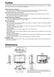
... regular vertical and horizontal intervals to facilitate composition. ■ REMOTE control Depending on the screen). • Time code display During HD SDI input, you can select to display VITC, LTC or UB time code. • Closed caption During VIDEO (NTSC) input, this feature to see video in its native resolution (that is equipped with a high performance 17.0-inch wide LCD display panel. ■ High performance LCD panel This monitor achieves outstanding color reproduction, a wide viewing angle...
... regular vertical and horizontal intervals to facilitate composition. ■ REMOTE control Depending on the screen). • Time code display During HD SDI input, you can select to display VITC, LTC or UB time code. • Closed caption During VIDEO (NTSC) input, this feature to see video in its native resolution (that is equipped with a high performance 17.0-inch wide LCD display panel. ■ High performance LCD panel This monitor achieves outstanding color reproduction, a wide viewing angle...

BTLH1760E User Guide
Page 9
... signal input line. The green LED light above the knob (amber) lights. from the AUDIO input terminal or SDI terminal (embedded audio). * Connecting headphones to FUNCTION5. * When the control lock is ON, the LED (green) lights up. FUNCTION5 : Confirms a menu item assigned to the HEADPHONES output connector turns off the speakers. 9 Volume knob Turn this knob to FUNCTION2. DVI-D : DVI-D input (HDCP compatible) * When using PC Input, select "RGB-COMP." It also confirms a menu item assigned to adjust speaker and headphones volume. Picture adjusting...
... signal input line. The green LED light above the knob (amber) lights. from the AUDIO input terminal or SDI terminal (embedded audio). * Connecting headphones to FUNCTION5. * When the control lock is ON, the LED (green) lights up. FUNCTION5 : Confirms a menu item assigned to the HEADPHONES output connector turns off the speakers. 9 Volume knob Turn this knob to FUNCTION2. DVI-D : DVI-D input (HDCP compatible) * When using PC Input, select "RGB-COMP." It also confirms a menu item assigned to adjust speaker and headphones volume. Picture adjusting...

BTLH1760E User Guide
Page 10
... terminal supports embedded audio. VIDEO terminal (BNC)*1*2 IN : This is the YPBPR/RGB signal input terminal. When using a GPI signal. DVI-D terminal (DVI-D) An HDCP compliant DVI-D signal input terminal. RS232C input terminal (D-SUB 9-pin) External control is possible by using a PC RGB signal, connect the horizontal synchronizing signal to the SYNC/HD terminal, and the vertical synchronizing signal to a PC RGB signal. When multiple monitors are connected in a pair of the third device, and so on the screen...
... terminal supports embedded audio. VIDEO terminal (BNC)*1*2 IN : This is the YPBPR/RGB signal input terminal. When using a GPI signal. DVI-D terminal (DVI-D) An HDCP compliant DVI-D signal input terminal. RS232C input terminal (D-SUB 9-pin) External control is possible by using a PC RGB signal, connect the horizontal synchronizing signal to the SYNC/HD terminal, and the vertical synchronizing signal to a PC RGB signal. When multiple monitors are connected in a pair of the third device, and so on the screen...

BTLH1760E User Guide
Page 11
... power cover has been removed or opened, do not use the correct polarity. If a +12 V power supply is not longer than 2 m. Connect the power cord to the GND terminal, this could cause a fire or personal injury. 1 4 23 Pin number 1 2, 3 4 Signal GND - +12 V External DC input terminal 11 Power Supply Connecting and fixing the power cord 1. Using the power cord hook and the screw, attach the power cord to the monitor unit. ■ When using external DC power (12 V DC), check...
... power cover has been removed or opened, do not use the correct polarity. If a +12 V power supply is not longer than 2 m. Connect the power cord to the GND terminal, this could cause a fire or personal injury. 1 4 23 Pin number 1 2, 3 4 Signal GND - +12 V External DC input terminal 11 Power Supply Connecting and fixing the power cord 1. Using the power cord hook and the screw, attach the power cord to the monitor unit. ■ When using external DC power (12 V DC), check...

BTLH1760E User Guide
Page 12
.... 4. Signal format • Use "STATUS DISPLAY" in the "SYSTEM CONFIG" menu to set to "FILM." 5. Note: "UNSUPPORT SIGNAL" and "NO SIGNAL" may also indicate that appear on the screen can be properly displayed. Note: The status of information: input signal status, picture adjusting knob status, sharpness display, FUNCTION display, audio level meter display, menu display, time code display and closed caption display. Picture adjusting knob status Picture adjusting knob (J page 9, ) • Press or turn this knob to make adjustments...
.... 4. Signal format • Use "STATUS DISPLAY" in the "SYSTEM CONFIG" menu to set to "FILM." 5. Note: "UNSUPPORT SIGNAL" and "NO SIGNAL" may also indicate that appear on the screen can be properly displayed. Note: The status of information: input signal status, picture adjusting knob status, sharpness display, FUNCTION display, audio level meter display, menu display, time code display and closed caption display. Picture adjusting knob status Picture adjusting knob (J page 9, ) • Press or turn this knob to make adjustments...

BTLH1760E User Guide
Page 20
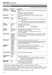
Selects type of the picture adjusting knob is fixed at 0. For VARICAM use "MODE2" for SD signal input. 4:3 display 16:9 display Sets under-scan and normal display. Sets vertical outline correction. With an Anamo lens and SDI 720/60P, 59.94P input, the picture is displayed. Normal display Under-scan *1 In split-screen display, changes are not reflected to the lower part of the screen. 1) VIDEO system input (VIDEO) (the factory defaults are SHARPNESS MODE: LOW and SHARPNESS...
Selects type of the picture adjusting knob is fixed at 0. For VARICAM use "MODE2" for SD signal input. 4:3 display 16:9 display Sets under-scan and normal display. Sets vertical outline correction. With an Anamo lens and SDI 720/60P, 59.94P input, the picture is displayed. Normal display Under-scan *1 In split-screen display, changes are not reflected to the lower part of the screen. 1) VIDEO system input (VIDEO) (the factory defaults are SHARPNESS MODE: LOW and SHARPNESS...

BTLH1760E User Guide
Page 21
... Adjusts the GAIN elements for RED.*2 Adjusts the GAIN elements for GREEN.*2 Adjusts the GAIN elements for BLUE.*2 Adjusts the BIAS elements for RED.*2 Adjusts the BIAS elements for GREEN.*2 Adjusts the BIAS elements for checking interlace status. ■ WB adjustment mode Select "VAR1" to a color temperature of the screen during adjustment. 21 The factory default is suitable for BLUE.*2 Resets "GAIN RED" - "BIAS BLUE" to "WHITE BALANCE VAR3" (WB) adjustments. Adjustable settings 0 - 63 (equivalent to a color temperature range...
... Adjusts the GAIN elements for RED.*2 Adjusts the GAIN elements for GREEN.*2 Adjusts the GAIN elements for BLUE.*2 Adjusts the BIAS elements for RED.*2 Adjusts the BIAS elements for GREEN.*2 Adjusts the BIAS elements for checking interlace status. ■ WB adjustment mode Select "VAR1" to a color temperature of the screen during adjustment. 21 The factory default is suitable for BLUE.*2 Resets "GAIN RED" - "BIAS BLUE" to "WHITE BALANCE VAR3" (WB) adjustments. Adjustable settings 0 - 63 (equivalent to a color temperature range...
BTLH1760E User Guide
Page 22
... the screen Left Bottom Right Bottom Right Top Left Top Sets display state for 3 seconds after a status change. Reduces the entire images for 60 seconds or longer. They save mode The backlight dims when no signal (NO SIGNAL) is turned on. Not displayed. Starts up using the factory defaults. Sets the studio standard color shade. and Canada: SMPTE-C, Others: EBU. 22 Adjusts LCD backlight brightness. Center of user data can be assigned to "FACTORY." *2 "H-POSITION", "V-POSITION...
... the screen Left Bottom Right Bottom Right Top Left Top Sets display state for 3 seconds after a status change. Reduces the entire images for 60 seconds or longer. They save mode The backlight dims when no signal (NO SIGNAL) is turned on. Not displayed. Starts up using the factory defaults. Sets the studio standard color shade. and Canada: SMPTE-C, Others: EBU. 22 Adjusts LCD backlight brightness. Center of user data can be assigned to "FACTORY." *2 "H-POSITION", "V-POSITION...

BTLH1760E User Guide
Page 23
...) FUNCTION Sub menu FUNCTION 1 FUNCTION 5 FUNCTION DISPLAY Settings HV DELAY AUTOSETUP BLUE ONLY GAMMA SELECT SD ASPECT SCAN SUB WINDOW WFM/VECTOR MARKER PIXEL TO PIXEL PIXEL POSITION LEVEL METER CROSS HATCH MONO TIME CODE CLOSED CAPTION UNDEF (Factory default: FUNCTION1: MARKER FUNCTION2: WFM/VECTOR FUNCTION3: PIXEL TO PIXEL FUNCTION4: TIME CODE FUNCTION5: LEVEL METER) OFF ON1 ON2 Underlined values indicate factory defaults. Displays synchronizing signals (horizontal, vertical). The display changes in the...
...) FUNCTION Sub menu FUNCTION 1 FUNCTION 5 FUNCTION DISPLAY Settings HV DELAY AUTOSETUP BLUE ONLY GAMMA SELECT SD ASPECT SCAN SUB WINDOW WFM/VECTOR MARKER PIXEL TO PIXEL PIXEL POSITION LEVEL METER CROSS HATCH MONO TIME CODE CLOSED CAPTION UNDEF (Factory default: FUNCTION1: MARKER FUNCTION2: WFM/VECTOR FUNCTION3: PIXEL TO PIXEL FUNCTION4: TIME CODE FUNCTION5: LEVEL METER) OFF ON1 ON2 Underlined values indicate factory defaults. Displays synchronizing signals (horizontal, vertical). The display changes in the...

BTLH1760E User Guide
Page 25
...] buttons.) To setup "IP MODE" (J page 20), exit the "SUB WINDOW" function first. • FULL Resizes the main window to which the "SUB WINDOW" function has been assigned to turn the function on and off. (This assumes that the "SUB WINDOW" function has been assigned to any of a recorded still image with live video. Normal window (main window) Press the button again Before image input...
...] buttons.) To setup "IP MODE" (J page 20), exit the "SUB WINDOW" function first. • FULL Resizes the main window to which the "SUB WINDOW" function has been assigned to turn the function on and off. (This assumes that the "SUB WINDOW" function has been assigned to any of a recorded still image with live video. Normal window (main window) Press the button again Before image input...
BTLH1760E User Guide
Page 30
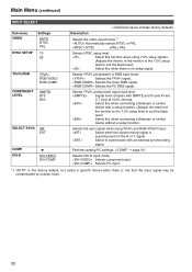
... DVI-D input mode. Selects PC input. *1 "AUTO" is the factory default, but select a specific format when there is superimposed on the G or Y signal. COMPONENT LEVEL SMPTE B75 B00 SELECT SYNC INT EXT COMP. Select to suit the black level) Select this when connecting a Betacam or similar device without a setup function. Selects the PC RGB signal. Main Menu (continued) INPUT SELECT Sub menu VIDEO NTSC SETUP Settings AUTO NTSC PAL 75 00 YPBPR/RGB...
... DVI-D input mode. Selects PC input. *1 "AUTO" is the factory default, but select a specific format when there is superimposed on the G or Y signal. COMPONENT LEVEL SMPTE B75 B00 SELECT SYNC INT EXT COMP. Select to suit the black level) Select this when connecting a Betacam or similar device without a setup function. Selects the PC RGB signal. Main Menu (continued) INPUT SELECT Sub menu VIDEO NTSC SETUP Settings AUTO NTSC PAL 75 00 YPBPR/RGB...

BTLH1760E User Guide
Page 34
.... The picture adjusting knob is disabled when the lock is engaged. Main Menu (continued) CONTROL Sub menu CONTROL Settings LOCAL REMOTE LOCAL ENABLE*2 DISABLE. All controls except [INPUT SELECT] and the volume knob are available when the lock is locked)*1 Selects the disabled operation on . "XXXXXX": 262800H (about 30 years), 262800 or greater number results in lock mode. Description Displays the number of hours. Disables all front panel operations. The volume knob (J page 9, used during lock engagement...
.... The picture adjusting knob is disabled when the lock is engaged. Main Menu (continued) CONTROL Sub menu CONTROL Settings LOCAL REMOTE LOCAL ENABLE*2 DISABLE. All controls except [INPUT SELECT] and the volume knob are available when the lock is locked)*1 Selects the disabled operation on . "XXXXXX": 262800H (about 30 years), 262800 or greater number results in lock mode. Description Displays the number of hours. Disables all front panel operations. The volume knob (J page 9, used during lock engagement...

BTLH1760E User Guide
Page 36
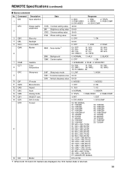
... VIDEO. Switches the input line to YPBPR/RGB. Sets the aspect ratio for SD signal input. (Disabled during HD and PC signal input) Switches the scan mode between "UNDER" and "NORMAL". (Disabled during PC signal input) Switches the gamma curve to 50%. GAMMA SEL. SDI1 INPUT SEL. Switches the input line to SDI1. G-TALLY*3 Lights the green tally. PIXEL TO PIXEL Switches screen display between color and monochrome (MONO). (Disabled during PC signal input) Lights the red tally. GPI Terminal (9P) Pin number 1 2 3 4 5 6 Signal...
... VIDEO. Switches the input line to YPBPR/RGB. Sets the aspect ratio for SD signal input. (Disabled during HD and PC signal input) Switches the scan mode between "UNDER" and "NORMAL". (Disabled during PC signal input) Switches the gamma curve to 50%. GAMMA SEL. SDI1 INPUT SEL. Switches the input line to SDI1. G-TALLY*3 Lights the green tally. PIXEL TO PIXEL Switches screen display between color and monochrome (MONO). (Disabled during PC signal input) Lights the red tally. GPI Terminal (9P) Pin number 1 2 3 4 5 6 Signal...

BTLH1760E User Guide
Page 38
... Input switch VPC 2 Image quality adjustment 3 OBO 4 OHV 5 VBL 6 DCH 7 DSD 8 ISM 9 IRF 10 ISM DMK Blue only HV Delay Backlight Cross hatch Status display Analog mode SELECT Sync DVI-D mode Marker settings 11 12 MGM MCT 13 VPC 14 15 MIP 16 OMO 17 MAS 18 MSC 19 MCO 20 MLE Gamma selection Color temperature settings Sharpness settings IP mode settings Monochrome settings SD aspect settings Scan settings Remote settings Remote operation settings Data...
... Input switch VPC 2 Image quality adjustment 3 OBO 4 OHV 5 VBL 6 DCH 7 DSD 8 ISM 9 IRF 10 ISM DMK Blue only HV Delay Backlight Cross hatch Status display Analog mode SELECT Sync DVI-D mode Marker settings 11 12 MGM MCT 13 VPC 14 15 MIP 16 OMO 17 MAS 18 MSC 19 MCO 20 MLE Gamma selection Color temperature settings Sharpness settings IP mode settings Monochrome settings SD aspect settings Scan settings Remote settings Remote operation settings Data...
BTLH1760E User Guide
Page 39
... × 768 (50 Hz) FF: UNSUPORT SIGNAL BT-LH1760 *1 When both 16:9 and 4:3 markers are displayed, the 16:9 marker state is returned. 39 QPC 2 Image quality adjustment CON : Contrast setting value BRI : Brightness setting value CRO : Chroma setting value 00-60 00-60 00-60 3 QBO 4 QBL 5 QCH Blue only Backlight Cross hatch PHA : Phase setting value 00-60 0: OFF 00-60...
... × 768 (50 Hz) FF: UNSUPORT SIGNAL BT-LH1760 *1 When both 16:9 and 4:3 markers are displayed, the 16:9 marker state is returned. 39 QPC 2 Image quality adjustment CON : Contrast setting value BRI : Brightness setting value CRO : Chroma setting value 00-60 00-60 00-60 3 QBO 4 QBL 5 QCH Blue only Backlight Cross hatch PHA : Phase setting value 00-60 0: OFF 00-60...
BTLH1760E User Guide
Page 41
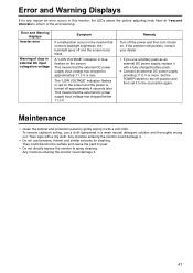
... power supply, replace it with a dry cloth. Set the POWER switch to the off the power and then turn it to the on . Remedy Turn off position and then set it back on position again. This means that controls backlight brightness, the backlight goes off approximately 4 seconds later. Then wipe with a soft cloth. Error and Warning displays Inverter error Warning of the error/warning. The "LOW VOLTAGE" indication flashes in red on the screen...
... power supply, replace it with a dry cloth. Set the POWER switch to the off the power and then turn it to the on . Remedy Turn off position and then set it back on position again. This means that controls backlight brightness, the backlight goes off approximately 4 seconds later. Then wipe with a soft cloth. Error and Warning displays Inverter error Warning of the error/warning. The "LOW VOLTAGE" indication flashes in red on the screen...
BTLH1760E User Guide
Page 42
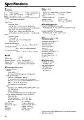
...; Signal level VIDEO EXT SYNC signal level: 0.3 Vp-p to 4.0 Vp-p HD/VD signal level: TTL level AUDIO AUDIO input level: 0.5 Vrms Speaker output: 0.5 W + 0.5 W Headphone output: 32 Ω, level adjustable ■ SDI embedded audio HD-SDI: SMPTE299M compatible Sampling rate: 48 kHz, synchronous/asynchronous 8 ch SD-SDI: SMPTE272M compatible Sampling rate: 48 kHz, synchronous 4 ch ■ Standard accessories Operationg instructions × 1 Warranty (Card) × 1 Power cord × 1 Power cord hook × 1 Screw × 1 Operationg instructions...
...; Signal level VIDEO EXT SYNC signal level: 0.3 Vp-p to 4.0 Vp-p HD/VD signal level: TTL level AUDIO AUDIO input level: 0.5 Vrms Speaker output: 0.5 W + 0.5 W Headphone output: 32 Ω, level adjustable ■ SDI embedded audio HD-SDI: SMPTE299M compatible Sampling rate: 48 kHz, synchronous/asynchronous 8 ch SD-SDI: SMPTE272M compatible Sampling rate: 48 kHz, synchronous 4 ch ■ Standard accessories Operationg instructions × 1 Warranty (Card) × 1 Power cord × 1 Power cord hook × 1 Screw × 1 Operationg instructions...


