
AJD750 User Guide
Page 2
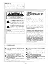
.... Cassette tape can be used for a length of time, protect it from dirt and dust. Refer any objects into the video cassette holder. Do not insert fingers or any needed servicing to authorized service personnel. -2- If the unit is the safety information. Do not leave a cassette in the recorder when not in which case the user will be used for either Color or Black & White recording. Cassette tape can...
.... Cassette tape can be used for a length of time, protect it from dirt and dust. Refer any objects into the video cassette holder. Do not insert fingers or any needed servicing to authorized service personnel. -2- If the unit is the safety information. Do not leave a cassette in the recorder when not in which case the user will be used for either Color or Black & White recording. Cassette tape can...
AJD750 User Guide
Page 3
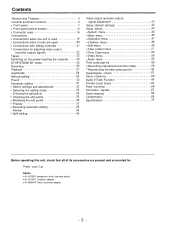
... menu 45 Connections when one unit is used 19 Operation menu 47 Connections when 2 units are used 20 Interface menu 48 Connections with editing controller 21 Edit menu 49 Connections for adjusting video output Tape protect menu 51 (encoder output) signals 22 Time Code menu 52 Tapes 23 Video menu 54 Switching on the power/inserting the cassette 24 Audio menu 55 STOP/STAND BY mode 25 Time code/user bit 58 Recording 26 Recording internal/external time codes 59 Playback 27 Reproducing the time code/user bit 60 Jog/shuttle 28 Superimpose screen 61 Manual...
... menu 45 Connections when one unit is used 19 Operation menu 47 Connections when 2 units are used 20 Interface menu 48 Connections with editing controller 21 Edit menu 49 Connections for adjusting video output Tape protect menu 51 (encoder output) signals 22 Time Code menu 52 Tapes 23 Video menu 54 Switching on the power/inserting the cassette 24 Audio menu 55 STOP/STAND BY mode 25 Time code/user bit 58 Recording 26 Recording internal/external time codes 59 Playback 27 Reproducing the time code/user bit 60 Jog/shuttle 28 Superimpose screen 61 Manual...
AJD750 User Guide
Page 4
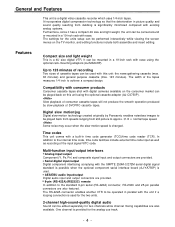
... minutes of recording Two sizes of consumer cassette tapes will not produce the smooth operation produced by Panasonic enables noiseless images to the standard 9-pin serial (RS-422A) connector, RS-232C and 25-pin parallel connectors are provided. Some noise may occur when the slow motion speed is a digital video cassette recorder which uses 1/4-inch tapes. General and Features This unit is changed. Multi-function input/output interfaces Analog input/output Component (Y, PB...
... minutes of recording Two sizes of consumer cassette tapes will not produce the smooth operation produced by Panasonic enables noiseless images to the standard 9-pin serial (RS-422A) connector, RS-232C and 25-pin parallel connectors are provided. Some noise may occur when the slow motion speed is a digital video cassette recorder which uses 1/4-inch tapes. General and Features This unit is changed. Multi-function input/output interfaces Analog input/output Component (Y, PB...

AJD750 User Guide
Page 5
... be performed. Menu-driven setup The setup settings, which are conducted prior to between -0.43 and 1 × normal tape speed. Features (continued) Dial jog/shuttle All playback is free of noise bars with jog operations performed when the variable range is set to operating the unit, are performed while viewing the screen menus either on the unit's display or a TV monitor. -5- Color images are welldefined even...
... be performed. Menu-driven setup The setup settings, which are conducted prior to between -0.43 and 1 × normal tape speed. Features (continued) Dial jog/shuttle All playback is free of noise bars with jog operations performed when the variable range is set to operating the unit, are performed while viewing the screen menus either on the unit's display or a TV monitor. -5- Color images are welldefined even...

AJD750 User Guide
Page 7
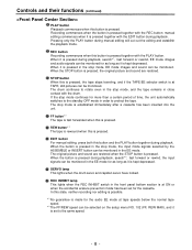
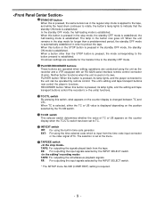
... USER SET is used to ANALOG. Amber: This lights when the error rate for the video and audio playback signals are inserted into this slot. AUTO OFF lamp This lights when trouble has arisen in accordance with adaptor are both acceptable. When the counter display indicates "CTL ", the display is switched on -screen menu. POWER switch When the ON side is pressed, the power is reset. The lamp lights when the eject...
... USER SET is used to ANALOG. Amber: This lights when the error rate for the video and audio playback signals are inserted into this slot. AUTO OFF lamp This lights when trouble has arisen in accordance with adaptor are both acceptable. When the counter display indicates "CTL ", the display is switched on -screen menu. POWER switch When the ON side is pressed, the power is reset. The lamp lights when the eject...
AJD750 User Guide
Page 8
... mode has been set to protect the tape. In this state, neither recording nor editing is possible. *1) No guarantee is made for as long as it is kept depressed. Pressing only the PLAY button during playback. The stop mode, the input mode signals selected by the ASSEMBLE or INSERT button can be monitored in the stop mode, EE mode images and sound can be selected on the setup menu...
... mode has been set to protect the tape. In this state, neither recording nor editing is possible. *1) No guarantee is made for as long as it is kept depressed. Pressing only the PLAY button during playback. The stop mode, the input mode signals selected by the ASSEMBLE or INSERT button can be monitored in the stop mode, EE mode images and sound can be selected on the setup menu...
AJD750 User Guide
Page 9
... operated by the INPUT SELECT switch. * The SETUP menu No.308 (CONFI EDIT) setting is automatically established in the stop mode for the transfer time to indicate that the standby ON mode is displayed depending on the counter display when the TC/CTL switch has been set at the menu. RECORDER button: When this button is pressed, its own. TAPE: For outputting the simultaneous playback signals. EE: For outputting the input signals selected by remote control...
... operated by the INPUT SELECT switch. * The SETUP menu No.308 (CONFI EDIT) setting is automatically established in the stop mode for the transfer time to indicate that the standby ON mode is displayed depending on the counter display when the TC/CTL switch has been set at the menu. RECORDER button: When this button is pressed, its own. TAPE: For outputting the simultaneous playback signals. EE: For outputting the input signals selected by remote control...

AJD750 User Guide
Page 10
... the search button has lighted. Shuttle mode: When the dial is turned and stopped at a particular position while the SHTL/SLOW switch is turned counterclockwise and the tape travels in the JOG mode. REV: This lights when the dial is at SHTL, the tape can be controlled from an external source using the controls on the operation of the search dial and SHTL/SLOW switch. REMOTE: Set to the REMOTE position. JOG...
... the search button has lighted. Shuttle mode: When the dial is turned and stopped at a particular position while the SHTL/SLOW switch is turned counterclockwise and the tape travels in the JOG mode. REV: This lights when the dial is at SHTL, the tape can be controlled from an external source using the controls on the operation of the search dial and SHTL/SLOW switch. REMOTE: Set to the REMOTE position. JOG...
AJD750 User Guide
Page 11
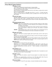
... point has been entered. TRIM buttons These buttons are pressed again. INSERT buttons Press one of these five buttons to select the input signals to be played back and monitored on -screen information and other messages. -11- Counter display This displays the TC and CTL count values, on the screen connected to the recorder. When this button is pressed for manual editing. When it is...
... point has been entered. TRIM buttons These buttons are pressed again. INSERT buttons Press one of these five buttons to select the input signals to be played back and monitored on -screen information and other messages. -11- Counter display This displays the TC and CTL count values, on the screen connected to the recorder. When this button is pressed for manual editing. When it is...

AJD750 User Guide
Page 12
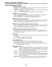
... recording and playback levels of the PCM audio signal CH1/CH2 and CUE track signals and the recording level of the digit now flashing on the display. START: This enters the data which means that they enable adjustment only when they are used to change the numeral of the composite video signals. Cassette insertion display lamp This lights when a cassette has been inserted into the unit. Input/output level controls These are connected...
... recording and playback levels of the PCM audio signal CH1/CH2 and CUE track signals and the recording level of the digit now flashing on the display. START: This enters the data which means that they enable adjustment only when they are used to change the numeral of the composite video signals. Cassette insertion display lamp This lights when a cassette has been inserted into the unit. Input/output level controls These are connected...

AJD750 User Guide
Page 13
... volumes are selected in turn in the following order: CH1, CH2, CUE and back to adjust the headphones volume and the monitor output volume. When these buttons are pressed together again, MIX is set on -screen menu No. 713, the display may not match the monitor output.) MONITOR SET button This is pressed, the signals output to CH1. Each time the "R" button is used to CH1. MONITOR SELECT switches...
... volumes are selected in turn in the following order: CH1, CH2, CUE and back to adjust the headphones volume and the monitor output volume. When these buttons are pressed together again, MIX is set on -screen menu No. 713, the display may not match the monitor output.) MONITOR SET button This is pressed, the signals output to CH1. Each time the "R" button is used to CH1. MONITOR SELECT switches...
AJD750 User Guide
Page 14
... control and switch (Composite output only variable.) When the ENCODER CONTROL switch is at LOCAL, the chroma level can be selected at MANUAL, the chroma level can be adjusted using this control. REC RUN: The time code runs only during recording when the RUN MODE switch has been set TC or UB to REGEN can be adjusted. When it is at the on the operation panel or by an external encoder/remote controller...
... control and switch (Composite output only variable.) When the ENCODER CONTROL switch is at LOCAL, the chroma level can be selected at MANUAL, the chroma level can be adjusted using this control. REC RUN: The time code runs only during recording when the RUN MODE switch has been set TC or UB to REGEN can be adjusted. When it is at the on the operation panel or by an external encoder/remote controller...

AJD750 User Guide
Page 17
... the unit is still operated in order to the power outlet using the power cord provided. The audio signals from a microphone can also be recorded by the internal time code generator is output. REF VIDEO IN connectors and 75 termination switch These are connected in a loop-through configuration. CUE OUT connector The analog signal recorded on -screen. MONITOR OUT connector During playback, the playback signals from the CUE track...
... the unit is still operated in order to the power outlet using the power cord provided. The audio signals from a microphone can also be recorded by the internal time code generator is output. REF VIDEO IN connectors and 75 termination switch These are connected in a loop-through configuration. CUE OUT connector The analog signal recorded on -screen. MONITOR OUT connector During playback, the playback signals from the CUE track...
AJD750 User Guide
Page 23
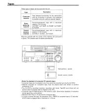
... not function when Consumer tape is 10 seconds for the camcorders used with the center of 123 minutes. (AJ-P64LP, AJ-94LP, AJ-P123LP) Align the cassette with the unit. Slow motion playback of 1 minute. -23- Maximum Still Timer is inserted in general. In order to another professional VTR. Only playback is engaged after a maximum of consumer format tapes may not be played...
... not function when Consumer tape is 10 seconds for the camcorders used with the center of 123 minutes. (AJ-P64LP, AJ-94LP, AJ-P123LP) Align the cassette with the unit. Slow motion playback of 1 minute. -23- Maximum Still Timer is inserted in general. In order to another professional VTR. Only playback is engaged after a maximum of consumer format tapes may not be played...
AJD750 User Guide
Page 26
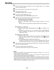
... PLAY lamps light, and recording commences. If it flashes or if it is offset from the playback pictures by 5 frames. -26- The input signals corresponding to the lighted lamps have been selected. 5-2 Adjusting the video level 1 Keep the VIDEO LEVEL PRESET/MANUAL switch set to "PRESET" (unity value). 2 To adjust the recording level, set the REC INHIBIT switch to place the unit in the stop mode. Check that the REC INHIBIT lamp is lighted during recording. Keep the audio input/output level controls...
... PLAY lamps light, and recording commences. If it flashes or if it is offset from the playback pictures by 5 frames. -26- The input signals corresponding to the lighted lamps have been selected. 5-2 Adjusting the video level 1 Keep the VIDEO LEVEL PRESET/MANUAL switch set to "PRESET" (unity value). 2 To adjust the recording level, set the REC INHIBIT switch to place the unit in the stop mode. Check that the REC INHIBIT lamp is lighted during recording. Keep the audio input/output level controls...

AJD750 User Guide
Page 28
...- The playback picture speed can also be transferred to the shuttle or jog mode when the search dial is played back at speeds other button. When the SHTL/SLOW switch has been set up so that the JOG lamp lights. To transfer from the jog mode to another mode, press the STOP button or other than -0.43 to +1 × normal speed. Immediately after the power has been turned on the...
...- The playback picture speed can also be transferred to the shuttle or jog mode when the search dial is played back at speeds other button. When the SHTL/SLOW switch has been set up so that the JOG lamp lights. To transfer from the jog mode to another mode, press the STOP button or other than -0.43 to +1 × normal speed. Immediately after the power has been turned on the...
AJD750 User Guide
Page 41
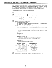
..., for instance, is to be error-free and accurate. (This adjustment must be repeated when one of the connecting cables has been replaced and whenever the connections are changed.) The adjustment procedure using an external encoder remote controller. Adjust the source machine independently. 3-1 When using the preset values Set the PRESET/MANUAL switches of the VIDEO LEVEL, CHROMA LEVEL, SETUP and HUE controls to PRESET. 3-2 When adjusting the video output signals without using this level to eliminate deviation.
..., for instance, is to be error-free and accurate. (This adjustment must be repeated when one of the connecting cables has been replaced and whenever the connections are changed.) The adjustment procedure using an external encoder remote controller. Adjust the source machine independently. 3-1 When using the preset values Set the PRESET/MANUAL switches of the VIDEO LEVEL, CHROMA LEVEL, SETUP and HUE controls to PRESET. 3-2 When adjusting the video output signals without using this level to eliminate deviation.

AJD750 User Guide
Page 45
... panel when the REMOTE/LOCAL switch has been set to REMOTE. 0: No buttons can be operated. 1: Only the STOP and EJECT buttons can be operated. 2: All buttons except for the RECORDER and PLAYER buttons can be set from 0 to automatic editing [PREVIEW, AUTO 15S EDIT], the unit will not operate if the preroll time is changed so that the characters are automatically displayed in a position on the screen. 002 CHARA...
... panel when the REMOTE/LOCAL switch has been set to REMOTE. 0: No buttons can be operated. 1: Only the STOP and EJECT buttons can be operated. 2: All buttons except for the RECORDER and PLAYER buttons can be set from 0 to automatic editing [PREVIEW, AUTO 15S EDIT], the unit will not operate if the preroll time is changed so that the characters are automatically displayed in a position on the screen. 002 CHARA...
AJD750 User Guide
Page 59
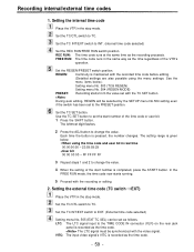
... start number of the VTR's operation. Setting the internal time code Place the VTR in the stop mode. REC RUN: The time code runs at the same time as the time code. FREE RUN: The time code runs in real time 00:00:00:00 - 23:59:59:29 User bit 00 00 00 00 - Set the REGEN/PRESET switch position. See the menu items below . The leftmost digit flashes. 2 Press the ADJ button to the TIME CODE IN...
... start number of the VTR's operation. Setting the internal time code Place the VTR in the stop mode. REC RUN: The time code runs at the same time as the time code. FREE RUN: The time code runs in real time 00:00:00:00 - 23:59:59:29 User bit 00 00 00 00 - Set the REGEN/PRESET switch position. See the menu items below . The leftmost digit flashes. 2 Press the ADJ button to the TIME CODE IN...
AJD750 User Guide
Page 60
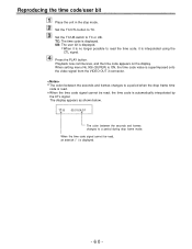
... , an asterisk ( * ) is automatically interpolated by the CTL signal. Set the TC/CTL button to TC or UB. Playback now commences, and the time code appears on the display. The display appears as shown below. Reproducing the time code/user bit Place the unit in the stop mode. Set the TC/UB switch to TC. Press the PLAY button. The colon between the seconds and frames...
... , an asterisk ( * ) is automatically interpolated by the CTL signal. Set the TC/CTL button to TC or UB. Playback now commences, and the time code appears on the display. The display appears as shown below. Reproducing the time code/user bit Place the unit in the stop mode. Set the TC/UB switch to TC. Press the PLAY button. The colon between the seconds and frames...


