Service Manual
Page 1
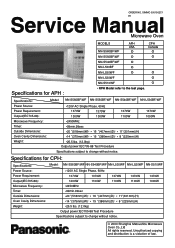
SIMMC 0001002C1 E1 Service Manual Microwave Oven Specifications for CPH: Specifications: Power Source: Power Requirement: Output(IEC705-88): Microwave Frequency: Timer: Outside Dimensions: Oven Cavity Dimensions: Weight: Model: NN-S560BF/WF NN-S540BF/WF NN-L530WF NN-L520WF NN-S510WF *120V AC Single Phase, 60Hz 1370W 1370W 1370W 1370W 1200W 1100W 1100W 1100W *2450MHz *99min.99sec *20 "(518mm...
SIMMC 0001002C1 E1 Service Manual Microwave Oven Specifications for CPH: Specifications: Power Source: Power Requirement: Output(IEC705-88): Microwave Frequency: Timer: Outside Dimensions: Oven Cavity Dimensions: Weight: Model: NN-S560BF/WF NN-S540BF/WF NN-L530WF NN-L520WF NN-S510WF *120V AC Single Phase, 60Hz 1370W 1370W 1370W 1370W 1200W 1100W 1100W 1100W *2450MHz *99min.99sec *20 "(518mm...
Service Manual
Page 2
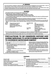
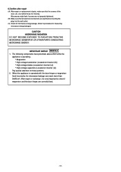
... does not contain warnings or cautions to advise non-technical individuals of dropping or abuse (C) Before turning on each oven prior to release to excessive microwave radiation. 3. Check for measuring radiation leakage." 4. IN U.S.A. (PASC) Panasonic Services Company 50 Meadowland Parkway, Secaucus, New Jersey 07094 IN PUERTO RICO (PSC) PSC San Gabriel Industrial Park...
... does not contain warnings or cautions to advise non-technical individuals of dropping or abuse (C) Before turning on each oven prior to release to excessive microwave radiation. 3. Check for measuring radiation leakage." 4. IN U.S.A. (PASC) Panasonic Services Company 50 Meadowland Parkway, Secaucus, New Jersey 07094 IN PUERTO RICO (PSC) PSC San Gabriel Industrial Park...
Service Manual
Page 3
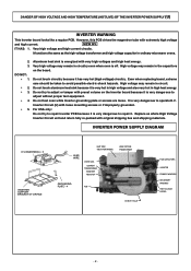
... dangerous to adjust without proper test equipment. Replace as the high voltage transformer and high voltage capacitor in circuitry even when oven is energized with original shipping box and shipping materials. Aluminum heat sink is off. Even when replacing board, extreme care ... High Voltage Inverter Circuit unit and return fully re-packed with very high voltages and high heat energy. High voltage may remain in ordinary microwave ovens. 2. 3. Do not try to repair Inverter PCB because it has very hot (high voltage) circuitry. INVERTER POWER SUPPLY DIAGRAM H.V INVERTER...
... dangerous to adjust without proper test equipment. Replace as the high voltage transformer and high voltage capacitor in circuitry even when oven is energized with original shipping box and shipping materials. Aluminum heat sink is off. Even when replacing board, extreme care ... High Voltage Inverter Circuit unit and return fully re-packed with very high voltages and high heat energy. High voltage may remain in ordinary microwave ovens. 2. 3. Do not try to repair Inverter PCB because it has very hot (high voltage) circuitry. INVERTER POWER SUPPLY DIAGRAM H.V INVERTER...
Service Manual
Page 6
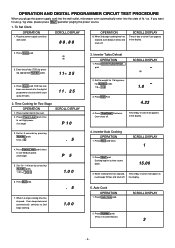
... Set Clock OPERATION 1. Press Clock pad. Inverter Auto Cooking OPERATION 1. SCROLL DISPLAY 2. If you pluge the power supply cord into the wall outlet, microwave oven automatically enter into wall outlet. Oven beeps twice and automatically switches to use g / kg state, please press Start pad after pluging the power source. 1. Press Inverter Turbo Defrost...
... Set Clock OPERATION 1. Press Clock pad. Inverter Auto Cooking OPERATION 1. SCROLL DISPLAY 2. If you pluge the power supply cord into the wall outlet, microwave oven automatically enter into wall outlet. Oven beeps twice and automatically switches to use g / kg state, please press Start pad after pluging the power source. 1. Press Inverter Turbo Defrost...
Service Manual
Page 10
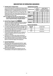
... of power relay B contacts in the display window. functions as shown in the DPC. 3. The digital programmer circuit controls the ON-OFF time of the microwave oven from the line voltage,120v 60Hz AC input. The relation between indications on the control panel and the output of the... microwave oven is tapped: (A) The digital programer circuit determines the power level and cooking time to complete cooking and indicates the operating state in order to "High" ...
... of power relay B contacts in the display window. functions as shown in the DPC. 3. The digital programmer circuit controls the ON-OFF time of the microwave oven from the line voltage,120v 60Hz AC input. The relation between indications on the control panel and the output of the... microwave oven is tapped: (A) The digital programer circuit determines the power level and cooking time to complete cooking and indicates the operating state in order to "High" ...
Service Manual
Page 11
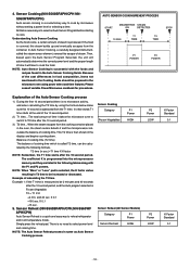
... time starts after the 10 second period. T2 time (in the oven, the steam sensor detects it takes the microwave oven to switch to cook by the following tables along with the foods and recipes found in the microwave oven using the formula below make sure this steam builds up and eventually escapes... from the T1 time. NOTE: When "More" or "Less" pad is a revolutionary way to T2 time after the 10 second period, and the Auto program selected is no microwave activity, and when...
... time starts after the 10 second period. T2 time (in the oven, the steam sensor detects it takes the microwave oven to switch to cook by the following tables along with the foods and recipes found in the microwave oven using the formula below make sure this steam builds up and eventually escapes... from the T1 time. NOTE: When "More" or "Less" pad is a revolutionary way to T2 time after the 10 second period, and the Auto program selected is no microwave activity, and when...
Service Manual
Page 12
... the grounding plate and screws. Do not operate on the cavity or any other appliances, the microwave oven is grounded properly before beginning repair work as an antenna and cause microwave leakage. DANGER OF HIGH VOLTAGE AND HIGH TEMPERATURE (HOT/LIVE) OF THE INVERTER POWER SUPPLY (U)...be used when grounded. otherwise, this H.V. WARNING OF DISCHARGING HIGH VOLTAGE CAPACITORS Warning about 30 seconds after the oven is designed to the output terminals. The microwave oven is turned off, an electric charge remains in the high voltage capacitors in the unit during operation.
... the grounding plate and screws. Do not operate on the cavity or any other appliances, the microwave oven is grounded properly before beginning repair work as an antenna and cause microwave leakage. DANGER OF HIGH VOLTAGE AND HIGH TEMPERATURE (HOT/LIVE) OF THE INVERTER POWER SUPPLY (U)...be used when grounded. otherwise, this H.V. WARNING OF DISCHARGING HIGH VOLTAGE CAPACITORS Warning about 30 seconds after the oven is designed to the output terminals. The microwave oven is turned off, an electric charge remains in the high voltage capacitors in the unit during operation.
Service Manual
Page 13
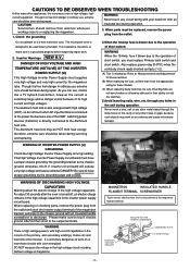
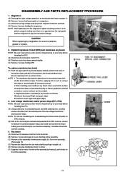
... of parts, make sure that all electrical connections are tight before inserting the plug into the wall outlet. (C) Check for microwave energy leakage. (Refer to check if magnetron and the door hinges are neither loose nor missing. After repair or exchange, ... DO NOT BECOME EXPOSED TO RADIATION FROM THE MICROWAVE GENERATOR OR OTHER PARTS CONDUCTING MICROWAVE ENERGY. Microwaves might leak if screws are not properly tightened. (B) Make sure that the screws of the oven, etc. When the appliance is operating.. *h Magnetron *h High voltage transformer (Located on Inverter (U)) *h ...
... of parts, make sure that all electrical connections are tight before inserting the plug into the wall outlet. (C) Check for microwave energy leakage. (Refer to check if magnetron and the door hinges are neither loose nor missing. After repair or exchange, ... DO NOT BECOME EXPOSED TO RADIATION FROM THE MICROWAVE GENERATOR OR OTHER PARTS CONDUCTING MICROWAVE ENERGY. Microwaves might leak if screws are not properly tightened. (B) Make sure that the screws of the oven, etc. When the appliance is operating.. *h Magnetron *h High voltage transformer (Located on Inverter (U)) *h ...
Service Manual
Page 14
...soldering iron, carefully remove all connectors from D.P.C. (B) Slide the escutcheon base upward slightly. (C) Remove 1 screws holding fan motor to prevent microwave leakage. SCREW - 13 - NOTE: Be sure to ground any static electric charge built up on your body before handling the DPC....magnetron, tighten mounting screws in place. 2. NOTE: After replacement of more than 30 watts on oven attaching orifice assembly. (C) Remove orifice assembly/Inverter power supply (U) from oven assembly. (Refer page 15) (D) Remove fan blade from DPC contacts, remove the defective transformer...
...soldering iron, carefully remove all connectors from D.P.C. (B) Slide the escutcheon base upward slightly. (C) Remove 1 screws holding fan motor to prevent microwave leakage. SCREW - 13 - NOTE: Be sure to ground any static electric charge built up on your body before handling the DPC....magnetron, tighten mounting screws in place. 2. NOTE: After replacement of more than 30 watts on oven attaching orifice assembly. (C) Remove orifice assembly/Inverter power supply (U) from oven assembly. (Refer page 15) (D) Remove fan blade from DPC contacts, remove the defective transformer...
Service Manual
Page 19
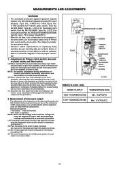
...by performing IEC standard test procedures. No. Completely tighten the screws holding the door hook assembly to ensure proper connection. 1. Set the oven for exactly one liter of tap water.Stir the water using the simple method outlined below . * Interlock switch replacement In replacing faulty switches...3C2-2 for Primary latch switch; fuse is as shown in table. Part No. G5J-1-TP for short switch and Part. Measurement of microwave output The output power of the magnetron can be sure mounting tabs are not bent, broken or otherwise deficient in their ability to hold...
...by performing IEC standard test procedures. No. Completely tighten the screws holding the door hook assembly to ensure proper connection. 1. Set the oven for exactly one liter of tap water.Stir the water using the simple method outlined below . * Interlock switch replacement In replacing faulty switches...3C2-2 for Primary latch switch; fuse is as shown in table. Part No. G5J-1-TP for short switch and Part. Measurement of microwave output The output power of the magnetron can be sure mounting tabs are not bent, broken or otherwise deficient in their ability to hold...
Service Manual
Page 20
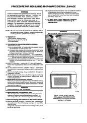
... measure for Canada) 1. After repairing or replacing any adjustment or repair to the surface being measured. (1) Measurement with a fully assembled oven. Government standard is 5 mW/cm2 while in a beaker which is installed and after measurement (A) After any radiation safety device, keep a...with the magnetron oscillating, measure the leakage by holding the probe perpendicular to a microwave oven, a leakage reading must be more than 2mW/cm2 (1mW/cm 2for Canada). (5) Leakage for a fully assembled oven [Before the latch switch (primary) is interrupted] while pulling the door .........
... measure for Canada) 1. After repairing or replacing any adjustment or repair to the surface being measured. (1) Measurement with a fully assembled oven. Government standard is 5 mW/cm2 while in a beaker which is installed and after measurement (A) After any radiation safety device, keep a...with the magnetron oscillating, measure the leakage by holding the probe perpendicular to a microwave oven, a leakage reading must be more than 2mW/cm2 (1mW/cm 2for Canada). (5) Leakage for a fully assembled oven [Before the latch switch (primary) is interrupted] while pulling the door .........
Service Manual
Page 21
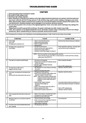
First of all . 2. No display and no operation at all operate the microwave oven following the correct operating procedures in order to find the exact cause of low voltage transformer). Open or loose lead wire harness 2. Defective primary ...wire harness 2. Shorted or open membrane key board 4. Defective secondary latch switch 1. Adjust door and latch switches. SYMPTOM 1. No display and no microwave oscillation. (No heat while oven lamp and fan motor turn on and turntable rotates when door is present on the digital programmer circuit (Terminals of power relay's and...
First of all . 2. No display and no operation at all operate the microwave oven following the correct operating procedures in order to find the exact cause of low voltage transformer). Open or loose lead wire harness 2. Defective primary ...wire harness 2. Shorted or open membrane key board 4. Defective secondary latch switch 1. Adjust door and latch switches. SYMPTOM 1. No display and no microwave oscillation. (No heat while oven lamp and fan motor turn on and turntable rotates when door is present on the digital programmer circuit (Terminals of power relay's and...
Service Manual
Page 23
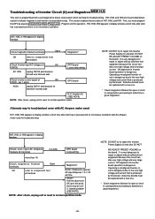
...high voltage and very large current. V. Troubleshooting of H97, H98, and H99. It is pressed and no microwave oscillation. Alternate way to troubleshoot oven with AC Ampere meter used for open or short to casing before proceeding to repair this board. This section ... 0.4-0.8A DPC board Loose wiring Check magnetron filament continuity Open OK refer to component test procedures Magnetron* NOTE: If filament is no microwave oscillation with a new one . * Check magnetron filament for operation. Defective boards must program the DPC by this Inverter Power Supply...
...high voltage and very large current. V. Troubleshooting of H97, H98, and H99. It is pressed and no microwave oscillation. Alternate way to troubleshoot oven with AC Ampere meter used for open or short to casing before proceeding to repair this board. This section ... 0.4-0.8A DPC board Loose wiring Check magnetron filament continuity Open OK refer to component test procedures Magnetron* NOTE: If filament is no microwave oscillation with a new one . * Check magnetron filament for operation. Defective boards must program the DPC by this Inverter Power Supply...

Service Manual
Page 24
...2 Q220 IC-220, RY-1 DISPLAY IC-1 IC-1 DISPLAY 1. Trouble Related to Digital Programmer Circuit SYMPTOM No display when oven is tapped No microwave oscillation at high power Q220 transistor Replace display and check operation Replace IC-1 and check operation 1 Unplug CN702(2 pin) ... Open (NOTE) CAUSE/CORRECTIONS STEP 2 Shorted Circuit of sensor Abnormal = 0V Normal > 10~30mV Steam sensor IC-1 - 23 - NEW H.V. Oven is detected, replace the defective parts. Replace DPC 2 Low voltage transformer (LVT) secondary voltage Abnormal 0V Normal LVT ➝ Step 3 3 IC...
...2 Q220 IC-220, RY-1 DISPLAY IC-1 IC-1 DISPLAY 1. Trouble Related to Digital Programmer Circuit SYMPTOM No display when oven is tapped No microwave oscillation at high power Q220 transistor Replace display and check operation Replace IC-1 and check operation 1 Unplug CN702(2 pin) ... Open (NOTE) CAUSE/CORRECTIONS STEP 2 Shorted Circuit of sensor Abnormal = 0V Normal > 10~30mV Steam sensor IC-1 - 23 - NEW H.V. Oven is detected, replace the defective parts. Replace DPC 2 Low voltage transformer (LVT) secondary voltage Abnormal 0V Normal LVT ➝ Step 3 3 IC...


