Service Manual
Page 1
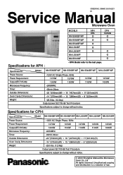
... E1 Service Manual Microwave Oven Specifications for CPH: Specifications: Power Source: Power Requirement: Output(IEC705-88): Microwave Frequency: Timer: Outside Dimensions: Oven Cavity Dimensions: Weight: Model: NN-S560BF/WF NN-S540BF/WF NN-L530WF NN-L520WF NN-S510WF *120V AC Single Phase, 60Hz 1370W 1370W 1370W 1370W 1200W 1100W 1100W 1100W *2450MHz *99min.99sec *20 "(518mm)(W)O 16 "(407mm)(D)O *14 "(375mm)(W)O 15 "(386mm)(D)O *26.5 lbs. (12.0kg) Output power:IEC705-88...
... E1 Service Manual Microwave Oven Specifications for CPH: Specifications: Power Source: Power Requirement: Output(IEC705-88): Microwave Frequency: Timer: Outside Dimensions: Oven Cavity Dimensions: Weight: Model: NN-S560BF/WF NN-S540BF/WF NN-L530WF NN-L520WF NN-S510WF *120V AC Single Phase, 60Hz 1370W 1370W 1370W 1370W 1200W 1100W 1100W 1100W *2450MHz *99min.99sec *20 "(518mm)(W)O 16 "(407mm)(D)O *14 "(375mm)(W)O 15 "(386mm)(D)O *26.5 lbs. (12.0kg) Output power:IEC705-88...
Service Manual
Page 2
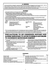
... 3 DISASSEMBLY AND PARTS REPLACEMENT PROCEDURE 13 CONTROL PANEL 3 COMPONENT TEST PROCEDURE 16 OPERATION AND DIGITAL PROGRAMMER MEASUREMENTS AND ADJUSTMENTS 18 CIRCUIT TEST PROCEDURE 5 PROCEDURE FOR MEASURING MICROWAVE ENERGY LEAKAGE...19 SCHEMATIC DIAGRAMS 7 TROUBLESHOOTING GUIDE 20 DESCRIPTION OF OPERATING SEQUENCE 9 EXPLODED VIEW AND PARTS LIST 24 CAUTIONS TO BE OBSERVED WHEN TROUBLESHOOTING ....11 SCHEMATIC DIAGRAM & PARTS LIST OF DIGITAL PROGRAMMER CIRCUIT 25 -1- > WARNING This service information is designed for experienced repair technicians only...
... 3 DISASSEMBLY AND PARTS REPLACEMENT PROCEDURE 13 CONTROL PANEL 3 COMPONENT TEST PROCEDURE 16 OPERATION AND DIGITAL PROGRAMMER MEASUREMENTS AND ADJUSTMENTS 18 CIRCUIT TEST PROCEDURE 5 PROCEDURE FOR MEASURING MICROWAVE ENERGY LEAKAGE...19 SCHEMATIC DIAGRAMS 7 TROUBLESHOOTING GUIDE 20 DESCRIPTION OF OPERATING SEQUENCE 9 EXPLODED VIEW AND PARTS LIST 24 CAUTIONS TO BE OBSERVED WHEN TROUBLESHOOTING ....11 SCHEMATIC DIAGRAM & PARTS LIST OF DIGITAL PROGRAMMER CIRCUIT 25 -1- > WARNING This service information is designed for experienced repair technicians only...
Service Manual
Page 3
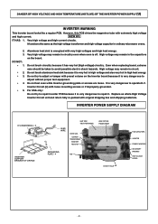
... circuits. It is energized with original shipping box and shipping materials. Very high voltage may remain in ordinary microwave ovens. 2. 3. DO NOT: * 1. * 2. * 3. * 4. * 5. Aluminum heat sink is very dangerous to avoid possible electric shock hazards. Even when replacing board, extreme care should be taken to operate H.V. DANGER OF HIGH VOLTAGE AND HIGH TEMPERATURE (HOT/LIVE) OF THE INVERTER POWER SUPPLY (U) INVERTER WARNING This Inverter...
... circuits. It is energized with original shipping box and shipping materials. Very high voltage may remain in ordinary microwave ovens. 2. 3. DO NOT: * 1. * 2. * 3. * 4. * 5. Aluminum heat sink is very dangerous to avoid possible electric shock hazards. Even when replacing board, extreme care should be taken to operate H.V. DANGER OF HIGH VOLTAGE AND HIGH TEMPERATURE (HOT/LIVE) OF THE INVERTER POWER SUPPLY (U) INVERTER WARNING This Inverter...
Service Manual
Page 5
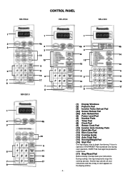
... (6) Number Pads (7) Timer Pad (8) Clock Pad (9) Sensor Cook Pad (10) Inverter Auto Cooking Pads (11) Quick Min Pad (12) More /Less Pad (13) Cooking Guide (14) Auto Cook Pad (15) Serving/Weight Pad (16) Start Pad One tap allows oven to restart oven. (17) Stop/Reset Pad Before cooking: One tap clears your instructions and time of day or colon appears on the display window. - 4 - If door is opened or STOP/RESET Pad is pressed once during oven operation, START...
... (6) Number Pads (7) Timer Pad (8) Clock Pad (9) Sensor Cook Pad (10) Inverter Auto Cooking Pads (11) Quick Min Pad (12) More /Less Pad (13) Cooking Guide (14) Auto Cook Pad (15) Serving/Weight Pad (16) Start Pad One tap allows oven to restart oven. (17) Stop/Reset Pad Before cooking: One tap clears your instructions and time of day or colon appears on the display window. - 4 - If door is opened or STOP/RESET Pad is pressed once during oven operation, START...
Service Manual
Page 6
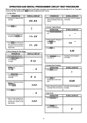
... use g / kg state, please press Start pad after pluging the power source. 1. Set the weight for 1 minute by pressing Number pads. 1 lb = 1 0 1.0 3. When 2nd stage cooking time has elapsed, oven beeps 5 times and shuts off . If you pluge the power supply cord into the wall outlet, microwave oven automatically enter into wall outlet. To Set Clock OPERATION 1. Press Power Level pad 46 times to set High power. (1st stage) SCROLL DISPLAY P 10 3. Inverter Turbo Defrost OPERATION 1. When cooking time has elapsed, oven beeps 5 times...
... use g / kg state, please press Start pad after pluging the power source. 1. Set the weight for 1 minute by pressing Number pads. 1 lb = 1 0 1.0 3. When 2nd stage cooking time has elapsed, oven beeps 5 times and shuts off . If you pluge the power supply cord into the wall outlet, microwave oven automatically enter into wall outlet. To Set Clock OPERATION 1. Press Power Level pad 46 times to set High power. (1st stage) SCROLL DISPLAY P 10 3. Inverter Turbo Defrost OPERATION 1. When cooking time has elapsed, oven beeps 5 times...
Service Manual
Page 10
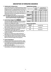
... digital programer circuit determines the power level and cooking time to complete cooking and indicates the operating state in the DPC to determine operating conditions and output necessary to control PWM signal to the inverter Power Supply to DC voltage immediately. 2. Then the half-wave doubler voltage rectifier circuit, consisting of the HV diodes and Capacitors, generates the necessary 4,000V DC needed for heating of microwave power since...
... digital programer circuit determines the power level and cooking time to complete cooking and indicates the operating state in the DPC to determine operating conditions and output necessary to control PWM signal to the inverter Power Supply to DC voltage immediately. 2. Then the half-wave doubler voltage rectifier circuit, consisting of the HV diodes and Capacitors, generates the necessary 4,000V DC needed for heating of microwave power since...
Service Manual
Page 11
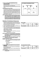
... memory and they are listed in sec.)=T1 time X K factor NOTE: Remember, the T1 time starts after the 10 second period, and the Auto program selected is covered, this escape of the Auto Sensor Cooking process 1) During the first 10 second period there is no microwave activity, and when calculating the T2 time by microwave without setting a power level or selecting a time. X 0.1 =160 sec. 4. Sensor Reheat (NN-S560BFAPH...
... memory and they are listed in sec.)=T1 time X K factor NOTE: Remember, the T1 time starts after the 10 second period, and the Auto program selected is covered, this escape of the Auto Sensor Cooking process 1) During the first 10 second period there is no microwave activity, and when calculating the T2 time by microwave without setting a power level or selecting a time. X 0.1 =160 sec. 4. Sensor Reheat (NN-S560BFAPH...
Service Manual
Page 12
... because of the Inverter. through the lamp holes on a 2-wire extension cord. This High Voltage Inverter Power Supply circuit board must be taken during operation. Please make sure it looks like a TV flyback transformer, however the current is free from danger in ordinary use , extreme care should remove their ability to or replacing the magnetron. 1. It is mandatory. MAGNETRON INSULATED HANDLE FILAMENT TERMINAL SCREWDRIVER Touch chassis side...
... because of the Inverter. through the lamp holes on a 2-wire extension cord. This High Voltage Inverter Power Supply circuit board must be taken during operation. Please make sure it looks like a TV flyback transformer, however the current is free from danger in ordinary use , extreme care should remove their ability to or replacing the magnetron. 1. It is mandatory. MAGNETRON INSULATED HANDLE FILAMENT TERMINAL SCREWDRIVER Touch chassis side...
Service Manual
Page 13
... if magnetron and the door hinges are tight before inserting the plug into the wall outlet. (C) Check for microwave energy leakage. (Refer to procedure for measuring microwave energy leakage.) CAUTION MICROWAVE RADIATION DO NOT BECOME EXPOSED TO RADIATION FROM THE MICROWAVE GENERATOR OR OTHER PARTS CONDUCTING MICROWAVE ENERGY. are neither loose nor missing. 6.Confirm after repair (A) After repair or replacement of the oven...
... if magnetron and the door hinges are tight before inserting the plug into the wall outlet. (C) Check for microwave energy leakage. (Refer to procedure for measuring microwave energy leakage.) CAUTION MICROWAVE RADIATION DO NOT BECOME EXPOSED TO RADIATION FROM THE MICROWAVE GENERATOR OR OTHER PARTS CONDUCTING MICROWAVE ENERGY. are neither loose nor missing. 6.Confirm after repair (A) After repair or replacement of the oven...
Service Manual
Page 14
... mounting screws in place. 2. NOTE: After replacement of membrane key board is cleaned sufficiently so that the surface of escutcheon base and peel off escutcheon sheet and membrane key board completely from the fan motor shaft by freeing 2 catch hooks on oven attaching orifice assembly. (C) Remove orifice assembly/Inverter power supply (U) from oven assembly. (Refer page 15) (D) Remove fan blade from escutcheon base. Fan motor (A) Disconnect 2 lead wires from fan motor terminals. (B) Remove 1 screw at located...
... mounting screws in place. 2. NOTE: After replacement of membrane key board is cleaned sufficiently so that the surface of escutcheon base and peel off escutcheon sheet and membrane key board completely from the fan motor shaft by freeing 2 catch hooks on oven attaching orifice assembly. (C) Remove orifice assembly/Inverter power supply (U) from oven assembly. (Refer page 15) (D) Remove fan blade from escutcheon base. Fan motor (A) Disconnect 2 lead wires from fan motor terminals. (B) Remove 1 screw at located...
Service Manual
Page 15
... or bend to inside so that the direction of steam sensor is achieved. Door assembly (A) Remove door C from door E by removing 1 screw. DOOR CCREEN B DOOR A DOOR KEY DOOR KEY SPRING DOOR E BASE DOOR C MOTOR COVER 01-046 - 14 - After replacement of the defective component parts of approximately 10°. (H) Place the door's lower hinge pin into the bottom hinge hole. (I) Use your finger to the turntable motor. (C) Remove the turntable motor by carefully pulling outward starting from upper right...
... or bend to inside so that the direction of steam sensor is achieved. Door assembly (A) Remove door C from door E by removing 1 screw. DOOR CCREEN B DOOR A DOOR KEY DOOR KEY SPRING DOOR E BASE DOOR C MOTOR COVER 01-046 - 14 - After replacement of the defective component parts of approximately 10°. (H) Place the door's lower hinge pin into the bottom hinge hole. (I) Use your finger to the turntable motor. (C) Remove the turntable motor by carefully pulling outward starting from upper right...
Service Manual
Page 16
... care not to touch any lead wire to inverter bracket. 8. Detach turntable wires from the oven. Make sure to securely tighten grounding screw from inverter. Take off outer panel. 6. Retighten 2 screw 10. Securely connect 3 lead wire connectors. 4. Remove 2 screws holding inverter to the aluminum heat sink because it is hot. 5. Slide and place assembly to inverter bracket A. 9. Remove screw and slide oriffice toward you, then lift up and out. 1. Inverter Power Supply (U) CAUTIONS WHILE REPLACING INVERTER POWER SUPPLY (U) 1. Remove screw...
... care not to touch any lead wire to inverter bracket. 8. Detach turntable wires from the oven. Make sure to securely tighten grounding screw from inverter. Take off outer panel. 6. Retighten 2 screw 10. Securely connect 3 lead wire connectors. 4. Remove 2 screws holding inverter to the aluminum heat sink because it is hot. 5. Slide and place assembly to inverter bracket A. 9. Remove screw and slide oriffice toward you, then lift up and out. 1. Inverter Power Supply (U) CAUTIONS WHILE REPLACING INVERTER POWER SUPPLY (U) 1. Remove screw...
Service Manual
Page 17
... which DO NOT TOUCH 4 were connected to use an AC line input current Ampere meter for 1 minute and press start . 1. Unplug 3 pin connector, CN701 B. After approximately 27 seconds, oven displays H97 and stops oven. 2. If both 1 and 2 are OK, the Inverter Power Supply (U) can only indicate an open ) 2. DO NOT TOUCH (HOT/HIGT VOLTAGE) HEAT SINK 1. To diagnose for an open . 1. During oven operation, input current...
... which DO NOT TOUCH 4 were connected to use an AC line input current Ampere meter for 1 minute and press start . 1. Unplug 3 pin connector, CN701 B. After approximately 27 seconds, oven displays H97 and stops oven. 2. If both 1 and 2 are OK, the Inverter Power Supply (U) can only indicate an open ) 2. DO NOT TOUCH (HOT/HIGT VOLTAGE) HEAT SINK 1. To diagnose for an open . 1. During oven operation, input current...
Service Manual
Page 19
... schematic diagram to the complexity of IEC test procedures, it in it for exactly one liter of the monitor circuit and all latch switches again by performing IEC standard test procedures. Set the oven for High power and heat it . L-2C2-2 for each model is completed. SWITCH GAP SHOULD BE Adjustment of glass cook plate. ANE6142-1450,Type No. fuse is recommended to test the magnetron using...
... schematic diagram to the complexity of IEC test procedures, it in it for exactly one liter of the monitor circuit and all latch switches again by performing IEC standard test procedures. Set the oven for High power and heat it . L-2C2-2 for each model is completed. SWITCH GAP SHOULD BE Adjustment of glass cook plate. ANE6142-1450,Type No. fuse is recommended to test the magnetron using...
Service Manual
Page 20
... 15cc (9ozss 1/2oz) of the oven. (B) Set the radiation monitor to 2450MHz and use the 2 inch (5cm) spacer supplied with the magnetron oscillating, measure the leakage by repair facility. WARNING AVOID CONTACTING ANY HIGH VOLTAGE PARTS. 01-035 MOVE PROBE ALONG SHADED AREA( )AROUND EXHAUST OPENINGS(as required by its manufacturer. After repairing or replacing any radiation safety device, keep...
... 15cc (9ozss 1/2oz) of the oven. (B) Set the radiation monitor to 2450MHz and use the 2 inch (5cm) spacer supplied with the magnetron oscillating, measure the leakage by repair facility. WARNING AVOID CONTACTING ANY HIGH VOLTAGE PARTS. 01-035 MOVE PROBE ALONG SHADED AREA( )AROUND EXHAUST OPENINGS(as required by its manufacturer. After repairing or replacing any radiation safety device, keep...
Service Manual
Page 21
... it has continuity, replace power relay B (RY-1)'s. 1. First of possible electrical shock hazard. SYMPTOM 1. Fuse is defective. Defective Inverter Power Supply (U) (Page 18) CORRECTIONS Check fan motor when thermal cutout is blown. 3. Open or loose wiring of high voltage circuit. 3. Oven takes longer time to operation procedure. TROUBLESHOOTING GUIDE CAUTION 1. Be careful of power relay B (RY-1) 5. Check continuity of primary, secondary latch switch and short switch including door. Adjust door and latch switches. When checking the...
... it has continuity, replace power relay B (RY-1)'s. 1. First of possible electrical shock hazard. SYMPTOM 1. Fuse is defective. Defective Inverter Power Supply (U) (Page 18) CORRECTIONS Check fan motor when thermal cutout is blown. 3. Open or loose wiring of high voltage circuit. 3. Oven takes longer time to operation procedure. TROUBLESHOOTING GUIDE CAUTION 1. Be careful of power relay B (RY-1) 5. Check continuity of primary, secondary latch switch and short switch including door. Adjust door and latch switches. When checking the...
Service Manual
Page 22
... secondary latch switch 2.Operation of thermal cutout 1.Open or loose wiring of turntable motor 2. Oven stops operation during cooking. 11. 7. Open or loose wiring of sensor terminal from DPC 2.Open steam sensor 3.Defective DPC Check tighten screws on the Auto sensor cooking mode. 1. Oven returns to plugged in mode after 10 seconds elapses on escutcheon base bracket, D.P.C. Loud buzzing noise can be heard. 9. board. Defective DPC mode as soon as start pad is pressed. 8. Loose fan and fan motor 1. Defective turntable motor 1.
... secondary latch switch 2.Operation of thermal cutout 1.Open or loose wiring of turntable motor 2. Oven stops operation during cooking. 11. 7. Open or loose wiring of sensor terminal from DPC 2.Open steam sensor 3.Defective DPC Check tighten screws on the Auto sensor cooking mode. 1. Oven returns to plugged in mode after 10 seconds elapses on escutcheon base bracket, D.P.C. Loud buzzing noise can be heard. 9. board. Defective DPC mode as soon as start pad is pressed. 8. Loose fan and fan motor 1. Defective turntable motor 1.
Service Manual
Page 23
... way to indicate magnetron and inverter circuit problem areas. It is produced by pressing Clock , Time , Start , Power Level . If all the above are the provided failure codes to troubleshoot oven with AC Ampere meter used H97, H98, H99 appears in display window Check oven input AC amperes measure at lead wire harness side DPC board H.V. Troubleshooting of H97, H98, and H99. Program unit for operation. H97, H98, H99...
... way to indicate magnetron and inverter circuit problem areas. It is produced by pressing Clock , Time , Start , Power Level . If all the above are the provided failure codes to troubleshoot oven with AC Ampere meter used H97, H98, H99 appears in display window Check oven input AC amperes measure at lead wire harness side DPC board H.V. Troubleshooting of H97, H98, and H99. Program unit for operation. H97, H98, H99...

Service Manual
Page 24
... are open , please replace DPC. 2. When the fuse pattern (PF2) opens. (1) Remove the jumper wire (PF1). (2) Insert the removed jumper wire (PF1) to "(PF4)" position and solder it . SYMPTOM No key input No beep sound Power relay A(RY-2) does not turn on RY-2 turns on metal surface of ZNR, L.V.T., Oven Lamp etc. DPC/Power Relay ➝ Step 2 DPC Magnetron TO BE CONTINUED FOR SENSOR MODELS Auto sensor cooking does not operate 1 normally. (Steam Sensor cooking...
... are open , please replace DPC. 2. When the fuse pattern (PF2) opens. (1) Remove the jumper wire (PF1). (2) Insert the removed jumper wire (PF1) to "(PF4)" position and solder it . SYMPTOM No key input No beep sound Power relay A(RY-2) does not turn on RY-2 turns on metal surface of ZNR, L.V.T., Oven Lamp etc. DPC/Power Relay ➝ Step 2 DPC Magnetron TO BE CONTINUED FOR SENSOR MODELS Auto sensor cooking does not operate 1 normally. (Steam Sensor cooking...

Service Manual
Page 27
... Part name & Description FAN MOTOR FAN BLADE AIR GUIDE A ORIFICE EXHAUST GUIDE B Pcs/ set 1 1 1 1 1 Remarks AC120V, SINGLE PHASE, 60Hz S560*F*PH A707S4T00AP F65434T00AP F612E9660AP ANE6142-1450 J61414T00AP STEAM SENSOR SENSOR BRACKET C INCANDESCENT LAMP(U) MICROSWITCH B MICROSWITCH A 1 S560*F*PH 1 S560*F*PH 1 125V, 60Hz, 20W 1 (V-16G-3C25L) 1 (D3V-16G-3C25) F61454050AP F66264T00CP A61785180AP A606Y4T00AP 2M261-M32F 2M261-M32G 2M258-M32F 2M258-M32G THERMAL CUTOUT THERMAL CUTOUT MOUNT MICROSWITCH C H.V.INVERTER (U) MAGNETRON MAGNETRON MAGNETRON MAGNETRON...
... Part name & Description FAN MOTOR FAN BLADE AIR GUIDE A ORIFICE EXHAUST GUIDE B Pcs/ set 1 1 1 1 1 Remarks AC120V, SINGLE PHASE, 60Hz S560*F*PH A707S4T00AP F65434T00AP F612E9660AP ANE6142-1450 J61414T00AP STEAM SENSOR SENSOR BRACKET C INCANDESCENT LAMP(U) MICROSWITCH B MICROSWITCH A 1 S560*F*PH 1 S560*F*PH 1 125V, 60Hz, 20W 1 (V-16G-3C25L) 1 (D3V-16G-3C25) F61454050AP F66264T00CP A61785180AP A606Y4T00AP 2M261-M32F 2M261-M32G 2M258-M32F 2M258-M32G THERMAL CUTOUT THERMAL CUTOUT MOUNT MICROSWITCH C H.V.INVERTER (U) MAGNETRON MAGNETRON MAGNETRON MAGNETRON...


