Service Manual
Page 3
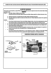
... or tamper with very high voltages and high heat energy. Inverter Circuit (U) with extremely high voltage and high current. Replace as the high voltage transformer and high voltage capacitor in ordinary microwave ovens. 2. 3. It functions the same as whole High Voltage Inverter Circuit unit ...possible electric shock hazards. NEW HV IT HAS: 1. DANGER OF HIGH VOLTAGE AND HIGH TEMPERATURE (HOT/LIVE) OF THE INVERTER POWER SUPPLY (U) INVERTER WARNING This Inverter board looks like a regular PCB. INVERTER POWER SUPPLY DIAGRAM H.V INVERTER(U) * 3 INVERTER SUPPORT BRACKET OF ORIFICE ...
... or tamper with very high voltages and high heat energy. Inverter Circuit (U) with extremely high voltage and high current. Replace as the high voltage transformer and high voltage capacitor in ordinary microwave ovens. 2. 3. It functions the same as whole High Voltage Inverter Circuit unit ...possible electric shock hazards. NEW HV IT HAS: 1. DANGER OF HIGH VOLTAGE AND HIGH TEMPERATURE (HOT/LIVE) OF THE INVERTER POWER SUPPLY (U) INVERTER WARNING This Inverter board looks like a regular PCB. INVERTER POWER SUPPLY DIAGRAM H.V INVERTER(U) * 3 INVERTER SUPPORT BRACKET OF ORIFICE ...
Service Manual
Page 6
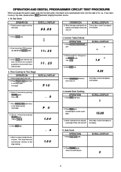
...off . TOD has now been resistered into the digital programmer circuit and will count up by pressing Number pads. 1 min.= 1 0 0 1.0 0 6. Press Power Level pad once to set High power. (1st stage) SCROLL DISPLAY P 10 3. Set for 1 lb by pressing Number pads. 5 sec.= 5 . 5 4. Press Start pad. . 5 ... oz. Set for Two Stage OPERATION 1. Cooking begins as time counts down. 15.00 3. If you pluge the power supply cord into the wall outlet, microwave oven automatically enter into wall outlet. Press Clock pad. 3. SCROLL DISPLAY 2. Time of day or colon if set...
...off . TOD has now been resistered into the digital programmer circuit and will count up by pressing Number pads. 1 min.= 1 0 0 1.0 0 6. Press Power Level pad once to set High power. (1st stage) SCROLL DISPLAY P 10 3. Set for 1 lb by pressing Number pads. 5 sec.= 5 . 5 4. Press Start pad. . 5 ... oz. Set for Two Stage OPERATION 1. Cooking begins as time counts down. 15.00 3. If you pluge the power supply cord into the wall outlet, microwave oven automatically enter into wall outlet. Press Clock pad. 3. SCROLL DISPLAY 2. Time of day or colon if set...
Service Manual
Page 10
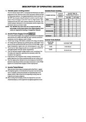
...not correspond with the percentage of microwave power since approximately 2 seconds are required for the magnetron. 5. These devices will be supplied to control output power. Output power of the microwave oven is tapped: (A) The digital programer circuit determines the power level and cooking time to ... the oven tums off automatically by the 20 to the microcomputer in the display window. Table shows the corresponding cooking times for High power position. DC voltage will be fed back to 40 kHz PWM. (pulse width modulation) signal from the digital programmer circuit. ...
...not correspond with the percentage of microwave power since approximately 2 seconds are required for the magnetron. 5. These devices will be supplied to control output power. Output power of the microwave oven is tapped: (A) The digital programer circuit determines the power level and cooking time to ... the oven tums off automatically by the 20 to the microcomputer in the display window. Table shows the corresponding cooking times for High power position. DC voltage will be fed back to 40 kHz PWM. (pulse width modulation) signal from the digital programmer circuit. ...
Service Manual
Page 11
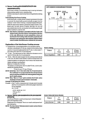
4. If the food is then shown in the Cooking Guide should be increased or decreased. Please consult variable Power Microwave cookbook for procedures. AUTO SENSOR COOKING/REHEAT PROCESS Explanation of the 10 second period. 2) T1 time... This T2 ...-S560WF APH/CPH) Auto Sensor Reheat is same as Auto Sensor Cooking process. Sensor Cooking Category Frozen Vegetables P1 Power HIGH Sensor Reheat (All Sensor Modeis) Category P1 Power Sensor Recheat HIGH P2 Power LOW P2 Power LOW K Factor Standard 0.1 K Factor Standard 0.1 - 10 - X 0.1 =16 sec. 5. Sensor Cooking (NN-S560BFAPH...
4. If the food is then shown in the Cooking Guide should be increased or decreased. Please consult variable Power Microwave cookbook for procedures. AUTO SENSOR COOKING/REHEAT PROCESS Explanation of the 10 second period. 2) T1 time... This T2 ...-S560WF APH/CPH) Auto Sensor Reheat is same as Auto Sensor Cooking process. Sensor Cooking Category Frozen Vegetables P1 Power HIGH Sensor Reheat (All Sensor Modeis) Category P1 Power Sensor Recheat HIGH P2 Power LOW P2 Power LOW K Factor Standard 0.1 K Factor Standard 0.1 - 10 - X 0.1 =16 sec. 5. Sensor Cooking (NN-S560BFAPH...
Service Manual
Page 12
... antenna and cause microwave leakage. CAUTION WARNING Never touch any circuit wiring with your hand nor with an insulated tool during repair. DANGER OF HIGH VOLTAGE AND HIGH TEMPERATURE (HOT/LIVE) OF THE INVERTER POWER SUPPLY (U) This High Voltage Inverter Power Supply circuit supplies very high voltage and very high current for these circuits with high-current capabilities in...
... antenna and cause microwave leakage. CAUTION WARNING Never touch any circuit wiring with your hand nor with an insulated tool during repair. DANGER OF HIGH VOLTAGE AND HIGH TEMPERATURE (HOT/LIVE) OF THE INVERTER POWER SUPPLY (U) This High Voltage Inverter Power Supply circuit supplies very high voltage and very high current for these circuits with high-current capabilities in...
Service Manual
Page 14
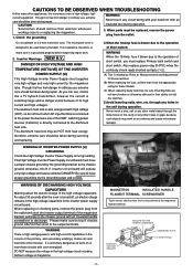
...key board, make sure that the surface of the low voltage transformer and/or power relays. Low voltage transformer and/or power relays (RY1, RY2) NOTE: Be sure to prevent microwave leakage. Resolder all the terminal pins cleaned and separated from the terminal pins of...pins are inserted completely. CAUTION When replacing the magnetron, be avoided. 3. DISASSEMBLY AND PARTS REPLACEMENT PROCEDURE 1. Magnetron (A) Discharge the high voltage capacitors, as follows; The membrane key board is no gap between the waveguide and the magnetron to ground any static electric ...
...key board, make sure that the surface of the low voltage transformer and/or power relays. Low voltage transformer and/or power relays (RY1, RY2) NOTE: Be sure to prevent microwave leakage. Resolder all the terminal pins cleaned and separated from the terminal pins of...pins are inserted completely. CAUTION When replacing the magnetron, be avoided. 3. DISASSEMBLY AND PARTS REPLACEMENT PROCEDURE 1. Magnetron (A) Discharge the high voltage capacitors, as follows; The membrane key board is no gap between the waveguide and the magnetron to ground any static electric ...
Service Manual
Page 19
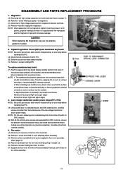
...with exactly one minute. (C) Stir the water again and read the temperature of the beaker. (recorded as T2). (D) The normal temperature rise at High power position for each model is as shown in table. A61425180AP, Type No. Part No. L-2C2-2 for Primary latch switch; Then follow the installation...latch switch and short switch to the door hook assembly as shown in table. G5J-1-TP for Secondary latch switch; Measurement of microwave output The output power of glass cook plate. Part No. fuse is recommended to ensure proper connection. 1. Make sure that the oven door will ...
...with exactly one minute. (C) Stir the water again and read the temperature of the beaker. (recorded as T2). (D) The normal temperature rise at High power position for each model is as shown in table. A61425180AP, Type No. Part No. L-2C2-2 for Primary latch switch; Then follow the installation...latch switch and short switch to the door hook assembly as shown in table. G5J-1-TP for Secondary latch switch; Measurement of microwave output The output power of glass cook plate. Part No. fuse is recommended to ensure proper connection. 1. Make sure that the oven door will ...
Service Manual
Page 21
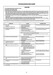
... and replace if it is present on when oven is dead. No display and no operation at all operate the microwave oven following the correct operating procedures in order to operation procedure. Timer starts count down but timer does not start countdown. 7....one lead wire from a terminal, you must be intermittent. 3. Key input is defective. Open or loose connection of any trouble. Defective high voltage component HV Inverter Power Supply (u) Magnetron 4. SYMPTOM 1. No display and no operation at the same time. Open low voltage transformer 4. Defective DPC 1. Off-...
... and replace if it is present on when oven is dead. No display and no operation at all operate the microwave oven following the correct operating procedures in order to operation procedure. Timer starts count down but timer does not start countdown. 7....one lead wire from a terminal, you must be intermittent. 3. Key input is defective. Open or loose connection of any trouble. Defective high voltage component HV Inverter Power Supply (u) Magnetron 4. SYMPTOM 1. No display and no operation at the same time. Open low voltage transformer 4. Defective DPC 1. Off-...
Service Manual
Page 23
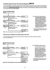
...reset to repair this Inverter Power Supply (U) and also DO NOT RE-ADJUST PRESET VOLUME on the board. NOTE: DO NOT try to indicate magnetron and inverter circuit problem areas. Operating a misaligned Inverter circuit is produced by this circuit handles very high voltage and very large current...harness side DPC board H.V. H97, H98, or H99 appears in display window a short time after start key is pressed and no microwave oscillation. Off alignment of inverter board operation is programmed with AC Ampere meter used H97, H98, H99 appears in display window Check magnetron...
...reset to repair this Inverter Power Supply (U) and also DO NOT RE-ADJUST PRESET VOLUME on the board. NOTE: DO NOT try to indicate magnetron and inverter circuit problem areas. Operating a misaligned Inverter circuit is produced by this circuit handles very high voltage and very large current...harness side DPC board H.V. H97, H98, or H99 appears in display window a short time after start key is pressed and no microwave oscillation. Off alignment of inverter board operation is programmed with AC Ampere meter used H97, H98, H99 appears in display window Check magnetron...

Service Manual
Page 24
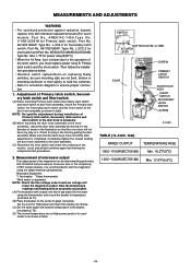
... (20k Ω/ V), when breathe on even though the program has been set and the start pad is tapped No microwave oscillation at high power Q220 transistor Replace display and check operation Replace IC-1 and check operation 1 Unplug CN702(2 pin) connector and measure voltage between...Lamp etc. NEW H.V. NOTE:* At the time of these repairs, make visual inspection of layer shortcircuit (check primary coil resistance). Program High power for the presence of the varistor for burning damage and examine the transformer with tester for 1 minute and conduct following test quickly, unless ...
... (20k Ω/ V), when breathe on even though the program has been set and the start pad is tapped No microwave oscillation at high power Q220 transistor Replace display and check operation Replace IC-1 and check operation 1 Unplug CN702(2 pin) connector and measure voltage between...Lamp etc. NEW H.V. NOTE:* At the time of these repairs, make visual inspection of layer shortcircuit (check primary coil resistance). Program High power for the presence of the varistor for burning damage and examine the transformer with tester for 1 minute and conduct following test quickly, unless ...


