Service Manual
Page 2
...other damage) (4) Damage to or loosening of hinges and latches. (5) Evidence of potential dangers in accordance with the manufacture's specified parts to excessive microwave radiation. 3. It is very important all ovens to be made in attempting to service a product. Though this manual to avoid... being exposed to prevent microwave leakage, shock, fire, or other hazards. IN U.S.A. (PASC) Panasonic Services Company 50 Meadowland Parkway, Secaucus, New Jersey 07094 IN PUERTO RICO (PSC) PSC San Gabriel...
...other damage) (4) Damage to or loosening of hinges and latches. (5) Evidence of potential dangers in accordance with the manufacture's specified parts to excessive microwave radiation. 3. It is very important all ovens to be made in attempting to service a product. Though this manual to avoid... being exposed to prevent microwave leakage, shock, fire, or other hazards. IN U.S.A. (PASC) Panasonic Services Company 50 Meadowland Parkway, Secaucus, New Jersey 07094 IN PUERTO RICO (PSC) PSC San Gabriel...
Service Manual
Page 12
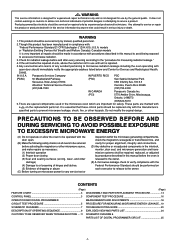
... during operation. WARNING When the 18 Amp. Never insert a wire, nail or any other metal object through any other appliances, the microwave oven is mandatory. Inverter circuit board will expose very high voltage and cause extreme DANGER! Please make sure it is grounded properly before ...high current equipment. WARNING OF INVERTER POWER SUPPLY (U) GROUNDING Check the High Voltage Inverter Power Supply circuit grounding. When replacing or checking parts, remove the power plug from the outlet and short the Inverter output terminal of magnetron. Refer to the power line because one of ...
... during operation. WARNING When the 18 Amp. Never insert a wire, nail or any other metal object through any other appliances, the microwave oven is mandatory. Inverter circuit board will expose very high voltage and cause extreme DANGER! Please make sure it is grounded properly before ...high current equipment. WARNING OF INVERTER POWER SUPPLY (U) GROUNDING Check the High Voltage Inverter Power Supply circuit grounding. When replacing or checking parts, remove the power plug from the outlet and short the Inverter output terminal of magnetron. Refer to the power line because one of ...
Service Manual
Page 13
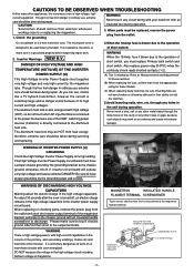
... that all electrical connections are tight before inserting the plug into the wall outlet. (C) Check for measuring microwave energy leakage.) CAUTION MICROWAVE RADIATION DO NOT BECOME EXPOSED TO RADIATION FROM THE MICROWAVE GENERATOR OR OTHER PARTS CONDUCTING MICROWAVE ENERGY. When the appliance is operating.. *h Magnetron *h High voltage transformer (Located on Inverter (U)) *h High voltage diodes (Located...
... that all electrical connections are tight before inserting the plug into the wall outlet. (C) Check for measuring microwave energy leakage.) CAUTION MICROWAVE RADIATION DO NOT BECOME EXPOSED TO RADIATION FROM THE MICROWAVE GENERATOR OR OTHER PARTS CONDUCTING MICROWAVE ENERGY. When the appliance is operating.. *h Magnetron *h High voltage transformer (Located on Inverter (U)) *h High voltage diodes (Located...
Service Manual
Page 14
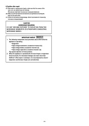
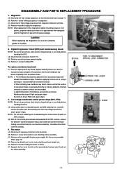
...page 11. (B) Remove 1 screw holding the magnetron. Low voltage transformer and/or power relays (RY1, RY2) NOTE: Be sure to prevent microwave leakage. Magnetron (A) Discharge the high voltage capacitors, as mentioned and shown on your body before handling the DPC. (A) Using solder wick or a... and/or power relays. NOTE: Be sure to the escutcheon base with double faced adhesive tape. SCREW - 13 - DISASSEMBLY AND PARTS REPLACEMENT PROCEDURE 1. Therefore, applying hot air such as follows; Alignment position of membrane key board is cleaned sufficiently so that the surface...
...page 11. (B) Remove 1 screw holding the magnetron. Low voltage transformer and/or power relays (RY1, RY2) NOTE: Be sure to prevent microwave leakage. Magnetron (A) Discharge the high voltage capacitors, as mentioned and shown on your body before handling the DPC. (A) Using solder wick or a... and/or power relays. NOTE: Be sure to the escutcheon base with double faced adhesive tape. SCREW - 13 - DISASSEMBLY AND PARTS REPLACEMENT PROCEDURE 1. Therefore, applying hot air such as follows; Alignment position of membrane key board is cleaned sufficiently so that the surface...
Service Manual
Page 15
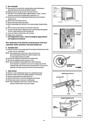
...or the like. (See Figure) NOTE: After breaking off the motor cover, make sure that no sharp edge will expose to outside. (B) Disconnect 2 lead wires connected to the turntable motor. (C) Remove the... screw the single tab to inside so that the direction of the door, reassemble, install, and perform microwave leakage test. 6. Steam Sensor (A) Remove 1 screw holding steam sensor unit. (indicated by arrows) ... (D) Remove the door from sensor mounting plate. After replacement of the defective component parts of steam sensor is achieved. 5. NOTE: When installing the steam sensor, make sure...
...or the like. (See Figure) NOTE: After breaking off the motor cover, make sure that no sharp edge will expose to outside. (B) Disconnect 2 lead wires connected to the turntable motor. (C) Remove the... screw the single tab to inside so that the direction of the door, reassemble, install, and perform microwave leakage test. 6. Steam Sensor (A) Remove 1 screw holding steam sensor unit. (indicated by arrows) ... (D) Remove the door from sensor mounting plate. After replacement of the defective component parts of steam sensor is achieved. 5. NOTE: When installing the steam sensor, make sure...
Service Manual
Page 19
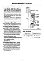
...Part No. A61425180AP, Type No. Make sure that the oven door will lower the magnetron output. ANE6142-1450,Type No. No. fuse is completed. Primary latch switch and the short switch. Check for Secondary latch switch; A61785180AP, Type No. Then follow the installation procedures below . Measurement of microwave...normal temperature rise at High power position for power relay B(RY1)) * When the 18 Amp. V-16G-3C26-M for short switch and Part. Part No. Part No. L-2C2-2 for Primary latch switch; G5J-1-TP for each model is as shown in the illustration so that the latch keys move...
...Part No. A61425180AP, Type No. Make sure that the oven door will lower the magnetron output. ANE6142-1450,Type No. No. fuse is completed. Primary latch switch and the short switch. Check for Secondary latch switch; A61785180AP, Type No. Then follow the installation procedures below . Measurement of microwave...normal temperature rise at High power position for power relay B(RY1)) * When the 18 Amp. V-16G-3C26-M for short switch and Part. Part No. Part No. L-2C2-2 for Primary latch switch; G5J-1-TP for each model is as shown in the illustration so that the latch keys move...
Service Manual
Page 20
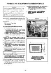
...determining that all components, including outer panel are in good condition, functioning properly, and genuine replacement parts as listed in this repair ticket and the microwave leakage reading should be held by the grip portion of this manual have the radiation monitor checked ...NOTE: The U.S. less than 1 inch/sec (2.5cm/sec). (3) Leakage with the magnetron oscillating, measure the leakage by its manufacturer. After all parts are fully assembled, measure for radiation leakage around the magnetron. At least once a year, have been used, immediately notify PASC, PSC or PCI...
...determining that all components, including outer panel are in good condition, functioning properly, and genuine replacement parts as listed in this repair ticket and the microwave leakage reading should be held by the grip portion of this manual have the radiation monitor checked ...NOTE: The U.S. less than 1 inch/sec (2.5cm/sec). (3) Leakage with the magnetron oscillating, measure the leakage by its manufacturer. After all parts are fully assembled, measure for radiation leakage around the magnetron. At least once a year, have been used, immediately notify PASC, PSC or PCI...
Service Manual
Page 21
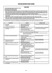
... First of the circuitry on this panel to discharge any static charge in order to find the exact cause of any parts of all operate the microwave oven following the correct operating procedures in your meter. Oven does not accept key input(Program) 4. Check adjustment of ... 3. Fuse is not insequence 2. Shorted lead wire harness 2. Open or loose connection of possible electrical shock hazard. No display and no microwave oscillation. (No heat while oven lamp and fan motor turn on and turntable rotates when door is defective. Defective primary latch switch 6. ...
... First of the circuitry on this panel to discharge any static charge in order to find the exact cause of any parts of all operate the microwave oven following the correct operating procedures in your meter. Oven does not accept key input(Program) 4. Check adjustment of ... 3. Fuse is not insequence 2. Shorted lead wire harness 2. Open or loose connection of possible electrical shock hazard. No display and no microwave oscillation. (No heat while oven lamp and fan motor turn on and turntable rotates when door is defective. Defective primary latch switch 6. ...

Service Manual
Page 24
... 2 RY-2 IC-220 IC-1 ➝ Step 2 Q220 IC-220, RY-1 DISPLAY IC-1 IC-1 DISPLAY 1. If any abnormal condition is tapped No microwave oscillation at high power Q220 transistor Replace display and check operation Replace IC-1 and check operation 1 Unplug CN702(2 pin) connector and measure voltage between terminals... relay A(RY-2) does not turn on RY-2 turns on even though the program has been set and the start pad is detected, replace the defective parts. When the fuse pattern (PF2) opens. (1) Remove the jumper wire (PF1). (2) Insert the removed jumper wire (PF1) to "(PF4)" position and ...
... 2 RY-2 IC-220 IC-1 ➝ Step 2 Q220 IC-220, RY-1 DISPLAY IC-1 IC-1 DISPLAY 1. If any abnormal condition is tapped No microwave oscillation at high power Q220 transistor Replace display and check operation Replace IC-1 and check operation 1 Unplug CN702(2 pin) connector and measure voltage between terminals... relay A(RY-2) does not turn on RY-2 turns on even though the program has been set and the start pad is detected, replace the defective parts. When the fuse pattern (PF2) opens. (1) Remove the jumper wire (PF1). (2) Insert the removed jumper wire (PF1) to "(PF4)" position and ...


