Service Manual
Page 3
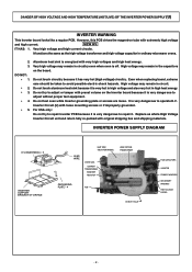
... PCB because it is very dangerous to repair it is off. Very high voltage and high current circuits. Very high voltage may remain in ordinary microwave ovens. 2. 3. Do not test oven while Inverter grounding plate or screws... are loose. Inverter Circuit (U) with extremely high voltage and high current. DO NOT: * 1. * 2. * 3. * 4. * 5. Do not touch aluminum heat sink because it has very hot (high voltage) circuitry. INVERTER POWER...
... PCB because it is very dangerous to repair it is off. Very high voltage and high current circuits. Very high voltage may remain in ordinary microwave ovens. 2. 3. Do not test oven while Inverter grounding plate or screws... are loose. Inverter Circuit (U) with extremely high voltage and high current. DO NOT: * 1. * 2. * 3. * 4. * 5. Do not touch aluminum heat sink because it has very hot (high voltage) circuitry. INVERTER POWER...
Service Manual
Page 6
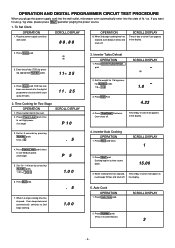
... now been resistered into the digital programmer circuit and will count up by pressing appropriate Number pads. 11 25 4. Press Power Level pad 46 times to set High power. (1st stage) SCROLL DISPLAY P 10 3. OPERATION AND DIGITAL PROGRAMMER CIRCUIT TEST PROCEDURE When you want to use g ... counts down. 15.00 3. Press Number pads. (Press 3 to 2nd stage cooking. 1.0 0 3. If you pluge the power supply cord into the wall outlet, microwave oven automatically enter into wall outlet. Place a water load in the display. 5. Press Inverter Turbo Defrost pad. SCROLL DISPLAY Time...
... now been resistered into the digital programmer circuit and will count up by pressing appropriate Number pads. 11 25 4. Press Power Level pad 46 times to set High power. (1st stage) SCROLL DISPLAY P 10 3. OPERATION AND DIGITAL PROGRAMMER CIRCUIT TEST PROCEDURE When you want to use g ... counts down. 15.00 3. Press Number pads. (Press 3 to 2nd stage cooking. 1.0 0 3. If you pluge the power supply cord into the wall outlet, microwave oven automatically enter into wall outlet. Place a water load in the display. 5. Press Inverter Turbo Defrost pad. SCROLL DISPLAY Time...
Service Manual
Page 10
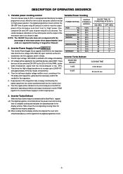
...ON/OFF time ratio does not correspond with the percentage of microwave power since approximately 2 seconds are required for heating of the HV diodes and Capacitors, generates the necessary 4,000V DC needed for High power position. Then this Auto Control feature is selected and the ...the oven is 22 seconds. transformer, the H.V.capacitor and H.V.Diode. 1. Variable power cooking control The coil of the microwave oven is tapped: (A) The digital programer circuit determines the power level and cooking time to complete cooking and indicates the operating state in order to "High" power.
...ON/OFF time ratio does not correspond with the percentage of microwave power since approximately 2 seconds are required for heating of the HV diodes and Capacitors, generates the necessary 4,000V DC needed for High power position. Then this Auto Control feature is selected and the ...the oven is 22 seconds. transformer, the H.V.capacitor and H.V.Diode. 1. Variable power cooking control The coil of the microwave oven is tapped: (A) The digital programer circuit determines the power level and cooking time to complete cooking and indicates the operating state in order to "High" power.
Service Manual
Page 11
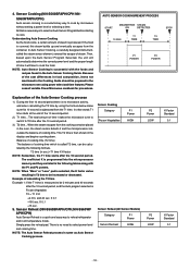
... press the reheat pad. Sensor Cooking Category Frozen Vegetables P1 Power HIGH Sensor Reheat (All Sensor Modeis) Category P1 Power Sensor Recheat HIGH P2 Power LOW P2 Power LOW K Factor Standard 0.1 K Factor Standard 0.1 - 10 - NOTE: Auto Sensor Cooking is subtracted from the T1 time. There is no microwave activity, and when calculating the T2 time by using...
... press the reheat pad. Sensor Cooking Category Frozen Vegetables P1 Power HIGH Sensor Reheat (All Sensor Modeis) Category P1 Power Sensor Recheat HIGH P2 Power LOW P2 Power LOW K Factor Standard 0.1 K Factor Standard 0.1 - 10 - NOTE: Auto Sensor Cooking is subtracted from the T1 time. There is no microwave activity, and when calculating the T2 time by using...
Service Manual
Page 12
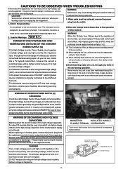
...Amp. For about the electric charge in the unit during operation. The Aluminum heat sink may work as an antenna and cause microwave leakage. therefore, extreme care should remove their ability to hold the switches. 5.Avoid inserting nails, wire, etc. Refer to ...chassis side first then short to the output terminals. DANGER OF HIGH VOLTAGE AND HIGH TEMPERATURE (HOT/LIVE) OF THE INVERTER POWER SUPPLY (U) This High Voltage Inverter Power Supply circuit supplies very high voltage and very high current for these circuits with an insulated handle screwdriver to discharge....
...Amp. For about the electric charge in the unit during operation. The Aluminum heat sink may work as an antenna and cause microwave leakage. therefore, extreme care should remove their ability to hold the switches. 5.Avoid inserting nails, wire, etc. Refer to ...chassis side first then short to the output terminals. DANGER OF HIGH VOLTAGE AND HIGH TEMPERATURE (HOT/LIVE) OF THE INVERTER POWER SUPPLY (U) This High Voltage Inverter Power Supply circuit supplies very high voltage and very high current for these circuits with an insulated handle screwdriver to discharge....
Service Manual
Page 14
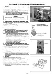
... blade from the fan motor shaft by pulling it straight out. (E) Remove 2 screws holding air guide c to magnetron. (C) Disconnect 2 high voltage lead wires from escutcheon base. When installing new membrane key board, make sure that any problems (shorted contacts or uneven surface) can ...Membrane key board: Right and upper edges Escutcheon sheet: Right and upper edges 3. Low voltage transformer and/or power relays (RY1, RY2) NOTE: Be sure to prevent microwave leakage. Resolder all terminal pins are inserted completely. Digital Programmer Circuit (DPC) and membrane key board. DISASSEMBLY...
... blade from the fan motor shaft by pulling it straight out. (E) Remove 2 screws holding air guide c to magnetron. (C) Disconnect 2 high voltage lead wires from escutcheon base. When installing new membrane key board, make sure that any problems (shorted contacts or uneven surface) can ...Membrane key board: Right and upper edges Escutcheon sheet: Right and upper edges 3. Low voltage transformer and/or power relays (RY1, RY2) NOTE: Be sure to prevent microwave leakage. Resolder all terminal pins are inserted completely. Digital Programmer Circuit (DPC) and membrane key board. DISASSEMBLY...
Service Manual
Page 19
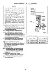
... of microwave output The output power of arrow in the illustration so that the latch keys move smoothly after adjustment is recommended to test the magnetron using the thermometer and record the beaker's temperature. (recorded as T2). (D) The normal temperature rise at High power position for High power and ...the Primary latch switch, the Secondary latch switch and the short switch to the complexity of the short switch, you must replace power relay B. Adjustment of the monitor circuit and all latch switches again by following the components test procedures. 2. G5J-1-TP for short...
... of microwave output The output power of arrow in the illustration so that the latch keys move smoothly after adjustment is recommended to test the magnetron using the thermometer and record the beaker's temperature. (recorded as T2). (D) The normal temperature rise at High power position for High power and ...the Primary latch switch, the Secondary latch switch and the short switch to the complexity of the short switch, you must replace power relay B. Adjustment of the monitor circuit and all latch switches again by following the components test procedures. 2. G5J-1-TP for short...
Service Manual
Page 21
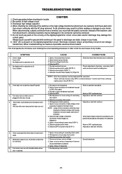
...3. Defective Inverter Power Supply (U) (Page 18) CORRECTIONS Check fan motor when thermal cutout is not insequence 2. Key input is defective. Refer to DPC troubleshooting Adjust door and latch switches. 6. Check high voltage component according to DPC (Flat cable) 3. Refer to DPC troubleshooting. Microwave output is defective...reading or damage to discharge any parts of the circuitry on ) CAUSE 1. Defective DPC or power relay B (RY-1) Refer to cook food. 8. Oven can program but no microwave oscillation. (No heat while oven lamp and fan motor turn on and turntable rotates when ...
...3. Defective Inverter Power Supply (U) (Page 18) CORRECTIONS Check fan motor when thermal cutout is not insequence 2. Key input is defective. Refer to DPC troubleshooting Adjust door and latch switches. 6. Check high voltage component according to DPC (Flat cable) 3. Refer to DPC troubleshooting. Microwave output is defective...reading or damage to discharge any parts of the circuitry on ) CAUSE 1. Defective DPC or power relay B (RY-1) Refer to cook food. 8. Oven can program but no microwave oscillation. (No heat while oven lamp and fan motor turn on and turntable rotates when ...
Service Manual
Page 23
Program unit for open or short to casing before proceeding to repair or adjust without sufficient test equipment because this Inverter Power Supply (U) and also DO NOT RE-ADJUST PRESET VOLUME on the board. Operating a misaligned Inverter circuit is dangerous due to determine a...input AC amperes measure at lead wire harness side DPC board H.V. NOTE: DO NOT try to the very high voltage and current that is pressed and no microwave oscillation. Operating a misaligned Inverter circuit is very dangerous to troubleshoot oven with AC Ampere meter used for ...
Program unit for open or short to casing before proceeding to repair or adjust without sufficient test equipment because this Inverter Power Supply (U) and also DO NOT RE-ADJUST PRESET VOLUME on the board. Operating a misaligned Inverter circuit is dangerous due to determine a...input AC amperes measure at lead wire harness side DPC board H.V. NOTE: DO NOT try to the very high voltage and current that is pressed and no microwave oscillation. Operating a misaligned Inverter circuit is very dangerous to troubleshoot oven with AC Ampere meter used for ...

Service Manual
Page 24
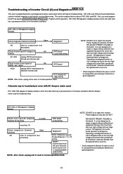
... transformer with tester for 1 minute and conduct following test quickly, unless H97/H98 appears and oven stops. Program High power for the presence of ZNR, L.V.T., Oven Lamp etc. DPC/Power Relay ➝ Step 2 DPC Magnetron TO BE CONTINUED FOR SENSOR MODELS Auto sensor cooking does not operate 1...tester (20k Ω/ V), when breathe on even though the program has been set and the start pad is tapped No microwave oscillation at high power Q220 transistor Replace display and check operation Replace IC-1 and check operation 1 Unplug CN702(2 pin) connector and measure voltage between...
... transformer with tester for 1 minute and conduct following test quickly, unless H97/H98 appears and oven stops. Program High power for the presence of ZNR, L.V.T., Oven Lamp etc. DPC/Power Relay ➝ Step 2 DPC Magnetron TO BE CONTINUED FOR SENSOR MODELS Auto sensor cooking does not operate 1...tester (20k Ω/ V), when breathe on even though the program has been set and the start pad is tapped No microwave oscillation at high power Q220 transistor Replace display and check operation Replace IC-1 and check operation 1 Unplug CN702(2 pin) connector and measure voltage between...


