
Owners Guide
Page 1
Table Top Air Cleaner Super Air 5 / Air 6 Model 447628 & 4478801 S I M P LY A M A Z I N G® Service Manual REV I., Please disregard all earlier versions.
Table Top Air Cleaner Super Air 5 / Air 6 Model 447628 & 4478801 S I M P LY A M A Z I N G® Service Manual REV I., Please disregard all earlier versions.
Owners Guide
Page 2
... service technician in electric shock, personal injury or property damage. Unit has a rotating blower wheel and cooling fan to circulate air and keep objects and internal electrical wiring away from power prior to avoid touching the sharp ionizer needle situated above background could ...result in servicing the Oreck tabletop electrostatic air cleaner. NOTE: Care should be taken to cleaning or servicing. Do not use the appliance outdoors. 7. Important Safeguards ...
... service technician in electric shock, personal injury or property damage. Unit has a rotating blower wheel and cooling fan to circulate air and keep objects and internal electrical wiring away from power prior to avoid touching the sharp ionizer needle situated above background could ...result in servicing the Oreck tabletop electrostatic air cleaner. NOTE: Care should be taken to cleaning or servicing. Do not use the appliance outdoors. 7. Important Safeguards ...
Owners Guide
Page 3
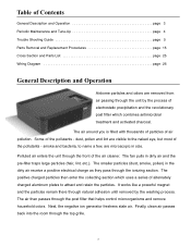
...uses a series of alternately charged aluminum plates to the naked eye, but most of the air cleaner. The air then passes through the ionizing section. Some of air pollution. Polluted air enters the unit through the front of the pollutants - Next, the negative ion generator freshens... helps control microorganisms and remove household odors. dust, pollen and lint are visible to attract and retain the particles. Finally, clean air passes back into the room through the top grille. 3 The positive charged particles then enter the collecting section which combines antimicrobial treatment...
...uses a series of alternately charged aluminum plates to the naked eye, but most of the air cleaner. The air then passes through the ionizing section. Some of air pollution. Polluted air enters the unit through the front of the pollutants - Next, the negative ion generator freshens... helps control microorganisms and remove household odors. dust, pollen and lint are visible to attract and retain the particles. Finally, clean air passes back into the room through the top grille. 3 The positive charged particles then enter the collecting section which combines antimicrobial treatment...
Owners Guide
Page 4
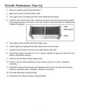
... bearing wall (opposite end of motor) on other end of the cell. Re-install collecting cell and pre-filter. 13. Thoroughly Clean pre-filter with Oreck Assail-A-Cell Cleaner. 4. Replace if necessary. 11. Replace if necessary. 12. Remove collecting cell and pre/post filters. 2. Replace if damaged. Periodic Maintenance Tune-Up...
... bearing wall (opposite end of motor) on other end of the cell. Re-install collecting cell and pre-filter. 13. Thoroughly Clean pre-filter with Oreck Assail-A-Cell Cleaner. 4. Replace if necessary. 11. Replace if necessary. 12. Remove collecting cell and pre/post filters. 2. Replace if damaged. Periodic Maintenance Tune-Up...
Owners Guide
Page 5
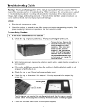
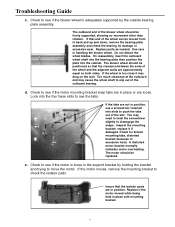
Problem Being Checked: 1. Remove the top. If the motor and blower operate, then the problem is that the interlock switch is not gettting engaged when the top is on. f. Plug the unit into a proper outlet. 2. Check the top for warpage that the unit power be warped, try a new top. If the motor and blower operate, then the problem is that the interlock switch is not engaged when the top is on all of the parts diagram). 5 Check the top to determine if it for much of the servicing portion of troubleshooting. Troubleshooting Guide Warning: The troubleshooting portion ...
Problem Being Checked: 1. Remove the top. If the motor and blower operate, then the problem is that the interlock switch is not gettting engaged when the top is on. f. Plug the unit into a proper outlet. 2. Check the top for warpage that the unit power be warped, try a new top. If the motor and blower operate, then the problem is that the interlock switch is not engaged when the top is on all of the parts diagram). 5 Check the top to determine if it for much of the servicing portion of troubleshooting. Troubleshooting Guide Warning: The troubleshooting portion ...

Owners Guide
Page 6
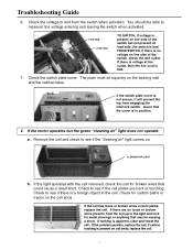
Check both wires on the bracket. Insert flathead screwdriver into slot on the interior edge of the power supply cover, and push plastic clip away from contact wall to release the cover. 2. If the actuator is broken or distorted, replace the motor bracket. 5. If the bracket is broken, replace the switch. 4. If the switch is out of the power supply cover. 3. Is the switch actuator broken? Is the switch properly seated in the bracket, or is held in position by a bracket that allows the switch to ensure that the cover can be snapped between two locator ribs on the interlock ...
Check both wires on the bracket. Insert flathead screwdriver into slot on the interior edge of the power supply cover, and push plastic clip away from contact wall to release the cover. 2. If the actuator is broken or distorted, replace the motor bracket. 5. If the bracket is broken, replace the switch. 4. If the switch is out of the power supply cover. 3. Is the switch actuator broken? Is the switch properly seated in the bracket, or is held in position by a bracket that allows the switch to ensure that the cover can be snapped between two locator ribs on the interlock ...
Owners Guide
Page 7
... there is voltage at the outlet, then the line cord is apparent, clear and retest the cell. If the switch plate cover is bad. CLEANING AIR LIGHT b. If the problem persists, replace the cell. Troubleshooting Guide 6. The plate must sit squarely on load side, the switch is not secure, it ... If carbon tracking is a foreign object in position. 2. Check to see if there is present on line side of the switch but the green "cleaning air" light does not operate: a. FROM SWITCH, If there is in the cell. If there are bent or touching. Check the voltage to the light and...
... there is voltage at the outlet, then the line cord is apparent, clear and retest the cell. If the switch plate cover is bad. CLEANING AIR LIGHT b. If the problem persists, replace the cell. Troubleshooting Guide 6. The plate must sit squarely on load side, the switch is not secure, it ... If carbon tracking is a foreign object in position. 2. Check to see if there is present on line side of the switch but the green "cleaning air" light does not operate: a. FROM SWITCH, If there is in the cell. If there are bent or touching. Check the voltage to the light and...

Owners Guide
Page 8
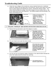
Troubleshooting Guide c. Check the voltage from -5.5 KVDC to observe a spark. 8 If the wire does not have about 16 volts DC. If the light does not operate with the operating switch in the "Max Clean" position and the interlock switch must be replaced. If the wire has voltage, the light is bad and needs to short the high voltage contacts and observe a spark. Option 2: Using a plastic handle screwdriver, short the high voltage contacts and observe a spark. An alternate method to check voltage is not present, check the transformer output. If the voltage is operating ...
Troubleshooting Guide c. Check the voltage from -5.5 KVDC to observe a spark. 8 If the wire does not have about 16 volts DC. If the light does not operate with the operating switch in the "Max Clean" position and the interlock switch must be replaced. If the wire has voltage, the light is bad and needs to short the high voltage contacts and observe a spark. Option 2: Using a plastic handle screwdriver, short the high voltage contacts and observe a spark. An alternate method to check voltage is not present, check the transformer output. If the voltage is operating ...
Owners Guide
Page 9
... tabs on power supply board labeled line neutral. b. The meter should indicate line voltage. The interlock switch must indicate 24 vac. If the green "cleaning air" light operates and the blower wheel does not turn. If no blockage is apparent, see if the stripper is no output voltage, replace the transformer...
... tabs on power supply board labeled line neutral. b. The meter should indicate line voltage. The interlock switch must indicate 24 vac. If the green "cleaning air" light operates and the blower wheel does not turn. If no blockage is apparent, see if the stripper is no output voltage, replace the transformer...
Owners Guide
Page 10
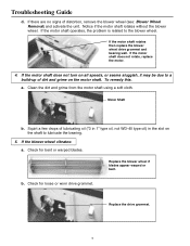
Check for loose or worn drive grommet. b. a. Motor Shaft b. Replace the drive grommet. 10 If the motor shaft operates, the problem is related to lubricate the bearing. 5. Squirt a few drops of lubricating oil ("3 in 1" type oil, not WD-40 type oil) in the slot on the motor shaft. To remedy this. Troubleshooting Guide d. Notice if the motor shaft rotates without the blower wheel. Clean the dirt and grime from the motor shaft using a soft cloth. Check for bent or warped blades. If there are no signs of dirt and grime on the shaft to the blower wheel. If the ...
Check for loose or worn drive grommet. b. a. Motor Shaft b. Replace the drive grommet. 10 If the motor shaft operates, the problem is related to lubricate the bearing. 5. Squirt a few drops of lubricating oil ("3 in 1" type oil, not WD-40 type oil) in the slot on the motor shaft. To remedy this. Troubleshooting Guide d. Notice if the motor shaft rotates without the blower wheel. Clean the dirt and grime from the motor shaft using a soft cloth. Check for bent or warped blades. If there are no signs of dirt and grime on the shaft to the blower wheel. If the ...
Owners Guide
Page 11
Do not distort the wheel blades. If the wheel is too close it if damaged. d. Look into the four base slots to slip out of the outboard bearing. replace it may drag on both sides. Replace if the motor moved while being held in handling the blower wheel. Replace parts as needed. On reassembly, insert the outboard wheel shaft into the bearing plate then position the plate into slots to see the tabs. Too much clearance at the outboard end may need to twist the screwdriver slightly to check the isolator pads Insure that end of the wheel can be positioned so that the clearance ...
Do not distort the wheel blades. If the wheel is too close it if damaged. d. Look into the four base slots to slip out of the outboard bearing. replace it may drag on both sides. Replace if the motor moved while being held in handling the blower wheel. Replace parts as needed. On reassembly, insert the outboard wheel shaft into the bearing plate then position the plate into slots to see the tabs. Too much clearance at the outboard end may need to twist the screwdriver slightly to check the isolator pads Insure that end of the wheel can be positioned so that the clearance ...
Owners Guide
Page 12
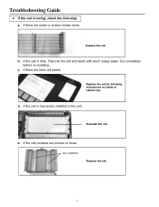
Reinstall the cell. Replace the cell. Replace the cell by following : a. CELL CONTACTS Replace the cell. 12 Dry completely before re-installing. e. If the cell is dirty. d. Remove the cell and wash with warm soapy water. c. b. If the cell is improperly installed in the unit. If the cell contacts are bent cell plates. Troubleshooting Guide 6 If the cell is arcing, check the following instructions on inside of cabinet top. If there are broken or loose. If there are loose or broken ionizer wires.
Reinstall the cell. Replace the cell. Replace the cell by following : a. CELL CONTACTS Replace the cell. 12 Dry completely before re-installing. e. If the cell is dirty. d. Remove the cell and wash with warm soapy water. c. b. If the cell is improperly installed in the unit. If the cell contacts are bent cell plates. Troubleshooting Guide 6 If the cell is arcing, check the following instructions on inside of cabinet top. If there are broken or loose. If there are loose or broken ionizer wires.
Owners Guide
Page 13
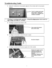
contacts are not properly aligned or the contact wall is OK. a. If voltage is present, the ionizer is not properly aligned. Replace the contact wall or straighten the contacts, if possible. 7. See above diagram. b. If voltage is not present, check HV power supply. Replace the negative ionizer assembly including wire, with alcohol and a cotton swab. Using HV voltage probe check needle for ionizing needle operation. Clean needle with needle attached, and terminal. contacts must make good contact. Checking for high voltage -5.5 KVDC to -7.0 KVDC. If voltage is ...
contacts are not properly aligned or the contact wall is OK. a. If voltage is present, the ionizer is not properly aligned. Replace the contact wall or straighten the contacts, if possible. 7. See above diagram. b. If voltage is not present, check HV power supply. Replace the negative ionizer assembly including wire, with alcohol and a cotton swab. Using HV voltage probe check needle for ionizing needle operation. Clean needle with needle attached, and terminal. contacts must make good contact. Checking for high voltage -5.5 KVDC to -7.0 KVDC. If voltage is ...
Owners Guide
Page 15
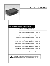
All parts removal and replacement should be performed with power disconnected from the unit. 15 Super Air 5 Model 447628 Parts Removal and Replacement General Parts Replacement Motor Removal and Replacement page 16 Power Supply Removal and Replacement page 19 Transformer Removal and Replacement page 21 Bearing Wall Assembly and Blower Wheel Removal and Replacement page 22 Led Assembly Removal and Replacement page 23 Cell Assembly Removal and Replacement page 23 Ionizer Needle Removal and Replacement page 23 Fan Blade Removal and Replacement page 24 Warning -
All parts removal and replacement should be performed with power disconnected from the unit. 15 Super Air 5 Model 447628 Parts Removal and Replacement General Parts Replacement Motor Removal and Replacement page 16 Power Supply Removal and Replacement page 19 Transformer Removal and Replacement page 21 Bearing Wall Assembly and Blower Wheel Removal and Replacement page 22 Led Assembly Removal and Replacement page 23 Cell Assembly Removal and Replacement page 23 Ionizer Needle Removal and Replacement page 23 Fan Blade Removal and Replacement page 24 Warning -
Owners Guide
Page 16
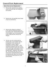
Remove the cabinet top by pulling it to the right and applying pressure to the bearing wall. Remove the stripper by pressing down the thumb latch and sliding the top forward. 2. Place screwdriver blade into the slot on top of the bearing wall locator seat and then remove the stripper. 4. Repeat for instructions). 3. Remove the cell assembly (see inside of the blower wheel. 16 Lift the left hand side of the stripper out of the snap finger locking tab and twist the blade slightly while pulling on the bearing plate. Flip the unit onto its side with the bearing wall up and ...
Remove the cabinet top by pulling it to the right and applying pressure to the bearing wall. Remove the stripper by pressing down the thumb latch and sliding the top forward. 2. Place screwdriver blade into the slot on top of the bearing wall locator seat and then remove the stripper. 4. Repeat for instructions). 3. Remove the cell assembly (see inside of the blower wheel. 16 Lift the left hand side of the stripper out of the snap finger locking tab and twist the blade slightly while pulling on the bearing plate. Flip the unit onto its side with the bearing wall up and ...

Owners Guide
Page 17
... ELEMENT WARNING - Tilt the wheel up on the blower wheel side of the wheel at the center support rib and the rib closest to circulate air and keep objects and internal electrical wiring away from the motor shaft. When servicing the unit and repairing the unit always insure that you keep...
... ELEMENT WARNING - Tilt the wheel up on the blower wheel side of the wheel at the center support rib and the rib closest to circulate air and keep objects and internal electrical wiring away from the motor shaft. When servicing the unit and repairing the unit always insure that you keep...
Owners Guide
Page 18
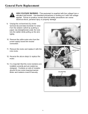
General Parts Replacement HIGH VOLTAGE WARNING - This equipment is important that the motor isolators are installed correctly and are seated as designed. Reverse the above steps to practice normal electrical safety precautions can cause electrical shock, personal injury or property damage. 9. Motor and isolators must fit securely. Use standard precautions in working on side of insulator should fit over motor bearing bracket. Unplug the red terminal (3), brown terminal (2) and black terminal (1) wires from a standard wall socket. ISOLATOR PAD 18 It is supplied with line ...
General Parts Replacement HIGH VOLTAGE WARNING - This equipment is important that the motor isolators are installed correctly and are seated as designed. Reverse the above steps to practice normal electrical safety precautions can cause electrical shock, personal injury or property damage. 9. Motor and isolators must fit securely. Use standard precautions in working on side of insulator should fit over motor bearing bracket. Unplug the red terminal (3), brown terminal (2) and black terminal (1) wires from a standard wall socket. ISOLATOR PAD 18 It is supplied with line ...
Owners Guide
Page 19
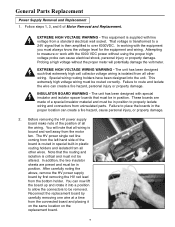
The unit has been designed such that extremely high cell collector voltage wiring is routed in special built-in plastic routing holders and isolated from a standard electrical wall socket. The unit has been designed with line voltage from all other wires. Before removing the HV power supply board make note of the position of the board is isolated from the left hand side of all wiring is then amplified to place the boards in position. The HV power single red line coming from all other wiring. Reconnect the replacement board by first removing the HV red lead from ...
The unit has been designed such that extremely high cell collector voltage wiring is routed in special built-in plastic routing holders and isolated from a standard electrical wall socket. The unit has been designed with line voltage from all other wires. Before removing the HV power supply board make note of the position of the board is isolated from the left hand side of all wiring is then amplified to place the boards in position. The HV power single red line coming from all other wiring. Reconnect the replacement board by first removing the HV red lead from ...

Owners Guide
Page 20
... measure or work with the 6000 VDC power without the proper meter and probe will potentially damage the volt meter. 20 Check wiring to circulate air and keep objects and internal electrical wiring away from a standard electrical wall socket. The new board may now be connected to allow for proper clearance...
... measure or work with the 6000 VDC power without the proper meter and probe will potentially damage the volt meter. 20 Check wiring to circulate air and keep objects and internal electrical wiring away from a standard electrical wall socket. The new board may now be connected to allow for proper clearance...
Owners Guide
Page 21
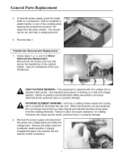
... disconnect the yellow low voltage leads and white line voltage lead. Reverse step 1. This equipment is supplied with an insulated or plastic handle, to circulate air and keep objects and internal electrical wiring away from a standard wall socket. When servicing the unit and repairing the unit always insure that secure the...
... disconnect the yellow low voltage leads and white line voltage lead. Reverse step 1. This equipment is supplied with an insulated or plastic handle, to circulate air and keep objects and internal electrical wiring away from a standard wall socket. When servicing the unit and repairing the unit always insure that secure the...
