
Owners Guide
Page 4
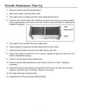
... bearing in collecting cell. Replace if damaged. Check to ensure rubber grommet on the shaft to ensure blower wheel rotates freely. 10. Replace if necessary. 12. Re-install collecting cell and pre-filter. 13. Wipe down inside of unit with a alcohol and a cotton swab. 7. Check for any bent plates in ...the bearing wall (opposite end of motor) on other end of the cell. Thoroughly Clean pre-filter with Oreck Assail-A-Cell Cleaner. 4. Squirt a few drops of machine oil ("3 in 1" type oil, not WD-40 type oil) in the plastic spacer at the center ...
... bearing in collecting cell. Replace if damaged. Check to ensure rubber grommet on the shaft to ensure blower wheel rotates freely. 10. Replace if necessary. 12. Re-install collecting cell and pre-filter. 13. Wipe down inside of unit with a alcohol and a cotton swab. 7. Check for any bent plates in ...the bearing wall (opposite end of motor) on other end of the cell. Thoroughly Clean pre-filter with Oreck Assail-A-Cell Cleaner. 4. Squirt a few drops of machine oil ("3 in 1" type oil, not WD-40 type oil) in the plastic spacer at the center ...
Owners Guide
Page 12
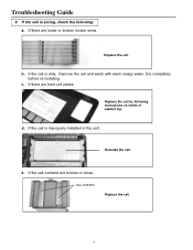
Remove the cell and wash with warm soapy water. If the cell contacts are bent cell plates. If the cell is arcing, check the following instructions on inside of cabinet top. Replace the cell. e. d. Reinstall the cell. Replace the cell by following : a. Troubleshooting Guide 6 If the cell is improperly installed in the unit. CELL CONTACTS Replace the cell. 12 If the cell is dirty. If there are broken or loose. If there are loose or broken ionizer wires. c. Dry completely before re-installing. b.
Remove the cell and wash with warm soapy water. If the cell contacts are bent cell plates. If the cell is arcing, check the following instructions on inside of cabinet top. Replace the cell. e. d. Reinstall the cell. Replace the cell by following : a. Troubleshooting Guide 6 If the cell is improperly installed in the unit. CELL CONTACTS Replace the cell. 12 If the cell is dirty. If there are broken or loose. If there are loose or broken ionizer wires. c. Dry completely before re-installing. b.
Owners Guide
Page 18
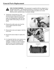
... by pushing a paper clip (straightened) under the wire into the switch while pulling on side of insulator should fit over motor bearing bracket. MOTOR WIRE 12. Contacts on the wire lightly. 10. Use standard precautions in working on it with line voltage applied. Remove the motor and replace it with the...
... by pushing a paper clip (straightened) under the wire into the switch while pulling on side of insulator should fit over motor bearing bracket. MOTOR WIRE 12. Contacts on the wire lightly. 10. Use standard precautions in working on it with line voltage applied. Remove the motor and replace it with the...
Owners Guide
Page 25
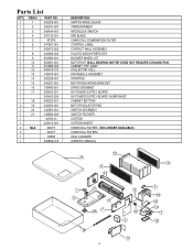
Parts List QTY ITEM # 1 1 1 2 1 3 1 4 2 5 1 6 1 7 1 8 1 9 1 10 1 11 1 12 1 13 1 14 1 15 1 16 1 17 1 1 18 2 19 1 20 1 21 1 1 2 NLA 3 1 1 PART NO. 242235-001 242331-007 242404-001 247135-001 AT2PK 247667-001 342472-002 ... "HUMP BACK" CABINET BOTTOM MOTOR ISOLATOR PAD SWITCH ASSEMBLY SWITCH ROCKER CARTON CARTON INSERT CHARCOAL FILTERS (NO LONGER AVAILABLE) CHARCOAL FILTERS CELL CLEANER OWNER'S MANUAL 12 11 5 8 14 1 21 6 9 20 7 18 25 13 16 2 17 3 15 19 10 4 19
Parts List QTY ITEM # 1 1 1 2 1 3 1 4 2 5 1 6 1 7 1 8 1 9 1 10 1 11 1 12 1 13 1 14 1 15 1 16 1 17 1 1 18 2 19 1 20 1 21 1 1 2 NLA 3 1 1 PART NO. 242235-001 242331-007 242404-001 247135-001 AT2PK 247667-001 342472-002 ... "HUMP BACK" CABINET BOTTOM MOTOR ISOLATOR PAD SWITCH ASSEMBLY SWITCH ROCKER CARTON CARTON INSERT CHARCOAL FILTERS (NO LONGER AVAILABLE) CHARCOAL FILTERS CELL CLEANER OWNER'S MANUAL 12 11 5 8 14 1 21 6 9 20 7 18 25 13 16 2 17 3 15 19 10 4 19
Owners Guide
Page 26
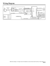
POWER BOOST SWITCH Wiring Diagram FUSE LINE CORD INTERLOCK SWITCH 120V, 60HZ POWER SWITCH BLK (HI) BRN (MED) RED (LO) BLACK (RIBBED) POWER SWITCH OUTPUT POS 1 OFF POS 2 L-1 POS 3 L-1,4 POS 4 L-2,4 POS 5 L-3,4 BLOWER WHT HV POWER SUPPLY BLACK (RIBBED) LINE NEW BLUE (242477-035) LED BLK 120V 24V WHT RED RED YEL YEL 12 LED BLUE (242477-035) ION./COLL. All trademarks are owned and used under the authority of Oreck Holdings, LLC. 75422-01 All rights reserved. CELL CONTACT WALL RED (142475-001) GRN GRN GRN RED GRN (242477-027) ©2004 Oreck Holdings, LLC.
POWER BOOST SWITCH Wiring Diagram FUSE LINE CORD INTERLOCK SWITCH 120V, 60HZ POWER SWITCH BLK (HI) BRN (MED) RED (LO) BLACK (RIBBED) POWER SWITCH OUTPUT POS 1 OFF POS 2 L-1 POS 3 L-1,4 POS 4 L-2,4 POS 5 L-3,4 BLOWER WHT HV POWER SUPPLY BLACK (RIBBED) LINE NEW BLUE (242477-035) LED BLK 120V 24V WHT RED RED YEL YEL 12 LED BLUE (242477-035) ION./COLL. All trademarks are owned and used under the authority of Oreck Holdings, LLC. 75422-01 All rights reserved. CELL CONTACT WALL RED (142475-001) GRN GRN GRN RED GRN (242477-027) ©2004 Oreck Holdings, LLC.