
Owner Manual
Page 1
... this product. All rights reserved. SN 29344659A * 2 9 3 4 4 6 5 9 A * QUICK SETUP Model : TX-SR606 Thank you for the AV component hookup. (C) Copyright 2008 ONKYO CORPORATION Japan. This quick setup sheet shows the typical hookup method for connecting speakers and AV components (DVD player, TV, cable/satellite receiver). For more detailed hookup information and operating instructions, please see the...
... this product. All rights reserved. SN 29344659A * 2 9 3 4 4 6 5 9 A * QUICK SETUP Model : TX-SR606 Thank you for the AV component hookup. (C) Copyright 2008 ONKYO CORPORATION Japan. This quick setup sheet shows the typical hookup method for connecting speakers and AV components (DVD player, TV, cable/satellite receiver). For more detailed hookup information and operating instructions, please see the...

Owner Manual
Page 2
.../ satellite Antenna input (e.g..RF IN) Assigning the Digital Input If there's no picture on the TX-SR606's display. On the front panel TUNING PRESET SETUP ENTER Digital audio signals received at HDMI IN inputs are not using the onscreen setup menus. If you are output by the...R SUB WOOFER DVD Please ensure the monitor input (VIDEO 1, VIDEO 2, VIDEO 3, etc.) selected corresponds to the AV receiver's COAXIAL 1 DIGITAL IN, and your TV or player doesn't support HDMI, use the TX-SR606's display when changing settings. IF NO HDMI IN 4 (GAME/TV) IN 3 (CBL/SAT) IN 2 HDMI ...
.../ satellite Antenna input (e.g..RF IN) Assigning the Digital Input If there's no picture on the TX-SR606's display. On the front panel TUNING PRESET SETUP ENTER Digital audio signals received at HDMI IN inputs are not using the onscreen setup menus. If you are output by the...R SUB WOOFER DVD Please ensure the monitor input (VIDEO 1, VIDEO 2, VIDEO 3, etc.) selected corresponds to the AV receiver's COAXIAL 1 DIGITAL IN, and your TV or player doesn't support HDMI, use the TX-SR606's display when changing settings. IF NO HDMI IN 4 (GAME/TV) IN 3 (CBL/SAT) IN 2 HDMI ...

Instruction Manual
Page 1
...you to obtain optimum performance and listening enjoyment from your AV components ....... 47 Listening to the Radio 51 Thank you for future reference. Following the instructions in the unit. AV Receiver TX-SR606 Instruction Manual Contents Introduction 2 Connection 14 Turning On ...& First Time Setup ..... 37 Basic Operation Playing your new AV Receiver. Please read this manual thoroughly before making connections and ...
...you to obtain optimum performance and listening enjoyment from your AV components ....... 47 Listening to the Radio 51 Thank you for future reference. Following the instructions in the unit. AV Receiver TX-SR606 Instruction Manual Contents Introduction 2 Connection 14 Turning On ...& First Time Setup ..... 37 Basic Operation Playing your new AV Receiver. Please read this manual thoroughly before making connections and ...

Instruction Manual
Page 3
...which can radiate radio frequency energy and, if not installed and used in your Onkyo dealer. 3. Make sure that interference will not occur in your Onkyo dealer. 6. Some models have it 's between the equipment and receiver. • Connect the equipment into an outlet on , so be determined ... in a particular installation. The power cord plug is illegal without the permission of the following measures: • Reorient or relocate the receiving antenna. • Increase the separation between 220 and 240 volts, set the selector to pack it how it was when you do ...
...which can radiate radio frequency energy and, if not installed and used in your Onkyo dealer. 3. Make sure that interference will not occur in your Onkyo dealer. 6. Some models have it 's between the equipment and receiver. • Connect the equipment into an outlet on , so be determined ... in a particular installation. The power cord plug is illegal without the permission of the following measures: • Reorient or relocate the receiving antenna. • Increase the separation between 220 and 240 volts, set the selector to pack it how it was when you do ...

Instruction Manual
Page 4
...personnel. GROEBENZELL, GERMANY K. The wire which is marked with the letter N or coloured black. For European Models Declaration of Conformity We, ONKYO EUROPE ELECTRONICS GmbH LIEGNITZERSTRASSE 6, 82194 GROEBENZELL, GERMANY declare in own responsibility, that indicated on packaging, the letter at the end of the product...or the BSI mark on the power supply cord of this adapter if your AC outlet does not match with the plug on the AV receiver's power cord. (Adapter varies from country to country.) *How to the terminal which is coloured brown must be connected to mount the...
...personnel. GROEBENZELL, GERMANY K. The wire which is marked with the letter N or coloured black. For European Models Declaration of Conformity We, ONKYO EUROPE ELECTRONICS GmbH LIEGNITZERSTRASSE 6, 82194 GROEBENZELL, GERMANY declare in own responsibility, that indicated on packaging, the letter at the end of the product...or the BSI mark on the power supply cord of this adapter if your AC outlet does not match with the plug on the AV receiver's power cord. (Adapter varies from country to country.) *How to the terminal which is coloured brown must be connected to mount the...

Instruction Manual
Page 5
...Player or Turntable 33 Connecting a Cassette, CDR, MiniDisc, or DAT Recorder 34 Connecting an RI Dock 35 Connecting Onkyo Components 36 Turning On the AV Receiver 37 Connecting the Power Cord 37 Turning On and Standby 37 First Time Setup 38 Automatic Speaker Setup 38 Speaker Settings...44 Changing the Input Display 45 Automatic Audio Input Selection Setup 46 Playing Your AV Components 47 Basic AV Receiver Operation 47 Common Functions 48 Setting the Display Brightness 48 Muting the AV Receiver 48 Using the Sleep Timer 48 Using Headphones 49 Displaying Source Information 49 ...
...Player or Turntable 33 Connecting a Cassette, CDR, MiniDisc, or DAT Recorder 34 Connecting an RI Dock 35 Connecting Onkyo Components 36 Turning On the AV Receiver 37 Connecting the Power Cord 37 Turning On and Standby 37 First Time Setup 38 Automatic Speaker Setup 38 Speaker Settings...44 Changing the Input Display 45 Automatic Audio Input Selection Setup 46 Playing Your AV Components 47 Basic AV Receiver Operation 47 Common Functions 48 Setting the Display Brightness 48 Muting the AV Receiver 48 Using the Sleep Timer 48 Using Headphones 49 Displaying Source Information 49 ...

Instruction Manual
Page 7
... listening room, a stereo speaker system in a second room, or Zone 2, as Dolby and DTS (pages 57-65). *While Powered Zone 2 is being used with this AV receiver-a surround-sound speaker system (up to 5.1-channels (see page 14). Front left and right speakers Main Room Surround back left and right speakers Left and...
... listening room, a stereo speaker system in a second room, or Zone 2, as Dolby and DTS (pages 57-65). *While Powered Zone 2 is being used with this AV receiver-a surround-sound speaker system (up to 5.1-channels (see page 14). Front left and right speakers Main Room Surround back left and right speakers Left and...

Instruction Manual
Page 8
... RETURN PHONES ZONE 2 OFF ZONE 2 LEVEL TONE MOVIE/TV MUSIC GAME DISPLAY DIGITAL INPUT DIMMER MEMORY TUNING MODE CLEAR SETUP MIC AUX INPUT VIDEO L AUDIO R AV RECEIVER TX-SR606 KL M Other models N OPQ RS TUV W ON/STANDBY STANDBY ZONE 2 TUNING PRESET X MASTER VOLUME PURE AUDIO MULTI CH DVD VCR/DVR CBL/SAT GAME/TV... ZONE 2 OFF ZONE 2 LEVEL TONE MOVIE/TV MUSIC GAME DISPLAY DIGITAL INPUT RT/PTY/TP MEMORY TUNING MODE CLEAR SETUP MIC AUX INPUT VIDEO L AUDIO R AV RECEIVER TX-SR606 Y T The actual front panel has various logos printed on page 9.
... RETURN PHONES ZONE 2 OFF ZONE 2 LEVEL TONE MOVIE/TV MUSIC GAME DISPLAY DIGITAL INPUT DIMMER MEMORY TUNING MODE CLEAR SETUP MIC AUX INPUT VIDEO L AUDIO R AV RECEIVER TX-SR606 KL M Other models N OPQ RS TUV W ON/STANDBY STANDBY ZONE 2 TUNING PRESET X MASTER VOLUME PURE AUDIO MULTI CH DVD VCR/DVR CBL/SAT GAME/TV... ZONE 2 OFF ZONE 2 LEVEL TONE MOVIE/TV MUSIC GAME DISPLAY DIGITAL INPUT RT/PTY/TP MEMORY TUNING MODE CLEAR SETUP MIC AUX INPUT VIDEO L AUDIO R AV RECEIVER TX-SR606 Y T The actual front panel has various logos printed on page 9.

Instruction Manual
Page 9
...the pages in parentheses. 1 SLEEP indicator (48) Lights up when the Sleep function has been set. 2 MUTING indicator (48) Flashes while the AV receiver is muted. 3 Listening mode and format indicators (57) Show the selected listening mode and audio input signal format. 4 Tuning indicators (52) FM ...radio. V TUNING MODE button (52) Selects the Auto or Manual tuning mode for automatic audio input selection setup. Getting to Know the AV Receiver-Continued For detailed information, see the pages in parentheses. The OFF button is selected. Goes off Zone 2. There are input jacks for...
...the pages in parentheses. 1 SLEEP indicator (48) Lights up when the Sleep function has been set. 2 MUTING indicator (48) Flashes while the AV receiver is muted. 3 Listening mode and format indicators (57) Show the selected listening mode and audio input signal format. 4 Tuning indicators (52) FM ...radio. V TUNING MODE button (52) Selects the Auto or Manual tuning mode for automatic audio input selection setup. Getting to Know the AV Receiver-Continued For detailed information, see the pages in parentheses. The OFF button is selected. Goes off Zone 2. There are input jacks for...

Instruction Manual
Page 10
... they are for connecting the front speakers, center, surround, and surround back speakers. They're assignable, which means you can be connected to Know the AV Receiver-Continued Rear Panel North American model 12 3 4 5 6G H I FRONT L/R, CENTER, SURR L/R, and SURR BACK L/R SPEAKERS These terminal posts are for connecting ...AM push terminals are connected digitally. See "HDMI Input Setup" on page 44. See "Bi-amping Front Speakers" on another -capable Onkyo component for connecting components with a coaxial digital audio output, such as a CD player or DVD player.
... they are for connecting the front speakers, center, surround, and surround back speakers. They're assignable, which means you can be connected to Know the AV Receiver-Continued Rear Panel North American model 12 3 4 5 6G H I FRONT L/R, CENTER, SURR L/R, and SURR BACK L/R SPEAKERS These terminal posts are for connecting ...AM push terminals are connected digitally. See "HDMI Input Setup" on page 44. See "Bi-amping Front Speakers" on another -capable Onkyo component for connecting components with a coaxial digital audio output, such as a CD player or DVD player.

Instruction Manual
Page 11
...A video component, such as a VCR or DVR, can be connected here for connecting a CD player's analog audio output. Getting to Know the AV Receiver-Continued Other models 12 3 4 5 6H I T U Only some models) This voltage selector provides compatibility with power systems around the world (see... page 3). N CBL/SAT IN A cable or satellite receiver can be connected here. S SUBWOOFER PRE OUT This analog audio output can be connected to the line inputs on amplifiers in Zone 2....
...A video component, such as a VCR or DVR, can be connected here for connecting a CD player's analog audio output. Getting to Know the AV Receiver-Continued Other models 12 3 4 5 6H I T U Only some models) This voltage selector provides compatibility with power systems around the world (see... page 3). N CBL/SAT IN A cable or satellite receiver can be connected here. S SUBWOOFER PRE OUT This analog audio output can be connected to the line inputs on amplifiers in Zone 2....

Instruction Manual
Page 12
.... K RETURN button Returns to On or Standby. You can also be controlled in Receiver mode (see the pages in this AV receiver. ■ Controlling the tuner To control the AV receiver's tuner, press the [TUNER] (or [RECEIVER]) REMOTE MODE button. Note: • An Onkyo cassette recorder connected via can select AM or FM by pressing the [TUNER...
.... K RETURN button Returns to On or Standby. You can also be controlled in Receiver mode (see the pages in this AV receiver. ■ Controlling the tuner To control the AV receiver's tuner, press the [TUNER] (or [RECEIVER]) REMOTE MODE button. Note: • An Onkyo cassette recorder connected via can select AM or FM by pressing the [TUNER...

Instruction Manual
Page 13
... or corrosion. • Expired batteries should be pressed continuously, thereby draining the batteries. • The remote controller may not work reliably if the AV receiver is subjected to prevent damage from leakage or corrosion. 30˚ 30˚ Approx. 16 ft. (5 m) Notes: • The remote controller... installed close to equipment that uses infrared rays, the remote controller may not work if there's an obstacle between it and the AV receiver's remote control sensor. 13 Notes: • If the remote controller doesn't work reliably, try replacing the batteries. • Don't ...
... or corrosion. • Expired batteries should be pressed continuously, thereby draining the batteries. • The remote controller may not work reliably if the AV receiver is subjected to prevent damage from leakage or corrosion. 30˚ 30˚ Approx. 16 ft. (5 m) Notes: • The remote controller... installed close to equipment that uses infrared rays, the remote controller may not work if there's an obstacle between it and the AV receiver's remote control sensor. 13 Notes: • If the remote controller doesn't work reliably, try replacing the batteries. • Don't ...

Instruction Manual
Page 14
Connecting Your Speakers Enjoying Home Theater Thanks to the AV receiver's superb capabilities, you can enjoy DVDs featuring Dolby Digital or DTS. With analog or digital TV, you can enjoy surround sound with a real sense of ... to add realistic ambience. The volume and quality of the bass output from the listener. You can enjoy Dolby Pro Logic IIx, DTS Neo:6, or Onkyo's original DSP listening modes. They enhance the realism of your listening room, and your own home-just like being in your listening position.
Connecting Your Speakers Enjoying Home Theater Thanks to the AV receiver's superb capabilities, you can enjoy DVDs featuring Dolby Digital or DTS. With analog or digital TV, you can enjoy surround sound with a real sense of ... to add realistic ambience. The volume and quality of the bass output from the listener. You can enjoy Dolby Pro Logic IIx, DTS Neo:6, or Onkyo's original DSP listening modes. They enhance the realism of your listening room, and your own home-just like being in your listening position.
Instruction Manual
Page 15
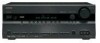
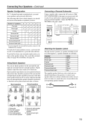
...CONTROL CD TAPE GAME/TV CBL/SAT VCR/DVR SUB WOOFER DVD LINE INPUT PRE OUT SUB WOOFER Attaching the Speaker Labels The AV receiver's positive (+) speaker terminals are all red. (The negative (-) speaker terminals are all black.) Speaker Front left Front right ... 6. Dipole speakers TV/screen 1 2 3 4 Normal speakers TV/screen 1 2 3 4 Connecting a Powered Subwoofer Using a suitable cable, connect the AV receiver's PRE OUT: SUBWOOFER to the corresponding speaker terminal. 5 65 6 7 8 1. Center speaker 4. Surround left and right dipole speakers should be positioned so...
...CONTROL CD TAPE GAME/TV CBL/SAT VCR/DVR SUB WOOFER DVD LINE INPUT PRE OUT SUB WOOFER Attaching the Speaker Labels The AV receiver's positive (+) speaker terminals are all red. (The negative (-) speaker terminals are all black.) Speaker Front left Front right ... 6. Dipole speakers TV/screen 1 2 3 4 Normal speakers TV/screen 1 2 3 4 Connecting a Powered Subwoofer Using a suitable cable, connect the AV receiver's PRE OUT: SUBWOOFER to the corresponding speaker terminal. 5 65 6 7 8 1. Center speaker 4. Surround left and right dipole speakers should be positioned so...

Instruction Manual
Page 16
... one cable to each pair of phase and will sound unnatural. • Unnecessarily long or very thin speaker cables may damage the AV receiver. • Don't connect more , but less than one surround back speaker, connect it to the left speaker Center speaker 16 Connecting...impedance, and use the amplifier at high volume levels for a long period of time, the built-in amp protection circuit may damage the AV receiver. • Don't connect a speaker to several terminals. Connect positive (+) terminals to only positive (+) terminals, and negative (-) terminals to "4 ohms...
... one cable to each pair of phase and will sound unnatural. • Unnecessarily long or very thin speaker cables may damage the AV receiver. • Don't connect more , but less than one surround back speaker, connect it to the left speaker Center speaker 16 Connecting...impedance, and use the amplifier at high volume levels for a long period of time, the built-in amp protection circuit may damage the AV receiver. • Don't connect a speaker to several terminals. Connect positive (+) terminals to only positive (+) terminals, and negative (-) terminals to "4 ohms...

Instruction Manual
Page 17
... terminal posts connect to the front speakers' woofer terminals. • Once you've completed the bi-amping connections shown below and turned on the AV receiver, you must set the Speaker Type setting to Bi-Amp to the right speaker's positive (+) woofer (low) terminal. Important: • When...remove the jumper bars that link the speakers' tweeter (high) and woofer (low) terminals. • Bi-amping can be used , the AV receiver is used with front speakers and surround back speakers respectively, or bi-amped to provide separate tweeter and woofer feeds for FRONT SPEAKERS L Left speaker...
... terminal posts connect to the front speakers' woofer terminals. • Once you've completed the bi-amping connections shown below and turned on the AV receiver, you must set the Speaker Type setting to Bi-Amp to the right speaker's positive (+) woofer (low) terminal. Important: • When...remove the jumper bars that link the speakers' tweeter (high) and woofer (low) terminals. • Bi-amping can be used , the AV receiver is used with front speakers and surround back speakers respectively, or bi-amped to provide separate tweeter and woofer feeds for FRONT SPEAKERS L Left speaker...

Instruction Manual
Page 18
..., as shown. (The antenna's wires are gripping the bare wires, not the insulation. Keep the antenna as far away as possible from your AV receiver is ready for use, you don't injure yourself when using it with a commercially available outdoor AM antenna (see page 19). 18 If you ...cannot achieve good reception with the supplied indoor FM antenna, try using thumbtacks. Push Insert wire Release AM ANTENNA Once your AV receiver, TV, speaker cables, and power cords. Caution: Be careful that the push terminals are not polarity sensitive, so they can be connected either...
..., as shown. (The antenna's wires are gripping the bare wires, not the insulation. Keep the antenna as far away as possible from your AV receiver is ready for use, you don't injure yourself when using it with a commercially available outdoor AM antenna (see page 19). 18 If you ...cannot achieve good reception with the supplied indoor FM antenna, try using thumbtacks. Push Insert wire Release AM ANTENNA Once your AV receiver, TV, speaker cables, and power cords. Caution: Be careful that the push terminals are not polarity sensitive, so they can be connected either...

Instruction Manual
Page 19
TV/FM antenna splitter To AV receiver To TV (or VCR) 19 Outdoor antenna AM loop antenna Insulated antenna cable AM ANTENNA Outdoor AM antennas work best outside , but usable results can ...
TV/FM antenna splitter To AV receiver To TV (or VCR) 19 Outdoor antenna AM loop antenna Insulated antenna cable AM ANTENNA Outdoor AM antennas work best outside , but usable results can ...

Instruction Manual
Page 20
Optical Digital Jacks The AV receiver's optical digital jacks have shutter-type covers that open when an optical plug is... and DTS. The audio quality is the same as for coaxial. Note: The AV receiver does not support SCART connections. 20 Use red plugs to connect left-channel audio inputs and outputs (typically labeled... BACK SUBWOOFER MULTI CH This cable carries multichannel analog audio and is inserted and close when it's removed. Push plugs in all AV connections. Left (white) Analog audio Left (white) Right (red) Right (red) (Yellow) Composite video (Yellow) Caution: ...
Optical Digital Jacks The AV receiver's optical digital jacks have shutter-type covers that open when an optical plug is... and DTS. The audio quality is the same as for coaxial. Note: The AV receiver does not support SCART connections. 20 Use red plugs to connect left-channel audio inputs and outputs (typically labeled... BACK SUBWOOFER MULTI CH This cable carries multichannel analog audio and is inserted and close when it's removed. Push plugs in all AV connections. Left (white) Analog audio Left (white) Right (red) Right (red) (Yellow) Composite video (Yellow) Caution: ...


