Owner Manual
Page 1
AV Receiver TX-SR504 TX-SR504E TX-SR8450 Instruction Manual Contents Introduction 2 Connection 16 Turning On & First Time Setup..... 32 Basic Operation Playing your AV components ....... 36 Listening to the Radio 38 Thank you to obtain optimum performance and listening enjoyment from your new AV Receiver. Enjoying the Listening Modes ..... 48 Advanced Operation 54 Troubleshooting 62 En Please retain this...
AV Receiver TX-SR504 TX-SR504E TX-SR8450 Instruction Manual Contents Introduction 2 Connection 16 Turning On & First Time Setup..... 32 Basic Operation Playing your AV components ....... 36 Listening to the Radio 38 Thank you to obtain optimum performance and listening enjoyment from your new AV Receiver. Enjoying the Listening Modes ..... 48 Advanced Operation 54 Troubleshooting 62 En Please retain this...
Owner Manual
Page 3
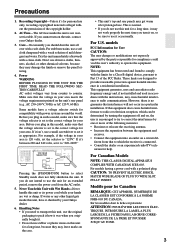
... OUT L 120V SUB WOOFER R VIDEO 2 VIDEO 1 SUB WOOFER DVD R FRONT SPEAKERS B L R VOLTAGE SELECTOR 120V AC OUTLET SWITCHED 100W MAX. AV RECEIVER 220-240V 220-240V Pressing the [STANDBY/ON] button to Part 15 of the FCC Rules. NOTE: This equipment has been tested and found to.... Handling Notes • If you should dust the unit all over with the instructions, may get warm after prolonged use the unit for your Onkyo dealer. 3. For models having a power cord with a clean cloth. Precautions 1. Don't use the original packaging to operate the equipment. For stubborn...
... OUT L 120V SUB WOOFER R VIDEO 2 VIDEO 1 SUB WOOFER DVD R FRONT SPEAKERS B L R VOLTAGE SELECTOR 120V AC OUTLET SWITCHED 100W MAX. AV RECEIVER 220-240V 220-240V Pressing the [STANDBY/ON] button to Part 15 of the FCC Rules. NOTE: This equipment has been tested and found to.... Handling Notes • If you should dust the unit all over with the instructions, may get warm after prolonged use the unit for your Onkyo dealer. 3. For models having a power cord with a clean cloth. Precautions 1. Don't use the original packaging to operate the equipment. For stubborn...

Owner Manual
Page 4
... AM loop antenna Power-plug adapter Only supplied in own responsibility, that indicated on the plug. For European Models Declaration of Conformity We, ONKYO EUROPE ELECTRONICS GmbH LIEGNITZERSTRASSE 6, 82194 GROEBENZELL, GERMANY declare in certain countries. If the fuse needs to be connected to the terminal which is... mounting of an AC plug on the power supply cord of this adapter if your AC outlet does not match with the plug on the AV receiver's power cord. (Adapter varies from country to country.) 1 2 3 Speaker Cable Speaker cable labels * In catalogs and on packaging, the letter at...
... AM loop antenna Power-plug adapter Only supplied in own responsibility, that indicated on the plug. For European Models Declaration of Conformity We, ONKYO EUROPE ELECTRONICS GmbH LIEGNITZERSTRASSE 6, 82194 GROEBENZELL, GERMANY declare in certain countries. If the fuse needs to be connected to the terminal which is... mounting of an AC plug on the power supply cord of this adapter if your AC outlet does not match with the plug on the AV receiver's power cord. (Adapter varies from country to country.) 1 2 3 Speaker Cable Speaker cable labels * In catalogs and on packaging, the letter at...

Owner Manual
Page 6
AV receiver SPEAKERS A B Remote controller or Speaker set A On Off Speaker set ...sound can be obtained by speaker set B On Off On Off Indicator AB A B Output Set A: 5.1 channels Set B: 2 channels Set A: 7.1 channels Set B: 2 channels No sound Speaker Set A: Main Room Front left and right speakers, making sound movements distinct and providing a ... Subwoofer The subwoofer handles the bass sounds of speakers with the AV receiver: speaker set A and speaker set B can use two sets of the LFE (LowFrequency Effects) channel. Their role in your TV facing forward at about 2-3 feet...
AV receiver SPEAKERS A B Remote controller or Speaker set A On Off Speaker set ...sound can be obtained by speaker set B On Off On Off Indicator AB A B Output Set A: 5.1 channels Set B: 2 channels Set A: 7.1 channels Set B: 2 channels No sound Speaker Set A: Main Room Front left and right speakers, making sound movements distinct and providing a ... Subwoofer The subwoofer handles the bass sounds of speakers with the AV receiver: speaker set A and speaker set B can use two sets of the LFE (LowFrequency Effects) channel. Their role in your TV facing forward at about 2-3 feet...

Owner Manual
Page 7
... MiniDisc, or DAT Recorder 30 Connecting the Power Cord of Another Component 30 Connecting Onkyo Components..........31 Connecting the Power Cord 31 Turning On & First Time Setup Turning On the AV Receiver 32 First Time Setup 33 Assigning Digital Inputs to Input Sources ....33 Changing the ...Configuration 34 Basic Operation Playing Your AV Components 36 Basic AV Receiver Operation 36 Using the Multichannel DVD Input 37 Displaying Source Information 37 Listening to the Radio 38 Listening to AM/FM stations 38 Presetting AM/FM Stations and XM Channels 39 Listening to XM Satellite ...
... MiniDisc, or DAT Recorder 30 Connecting the Power Cord of Another Component 30 Connecting Onkyo Components..........31 Connecting the Power Cord 31 Turning On & First Time Setup Turning On the AV Receiver 32 First Time Setup 33 Assigning Digital Inputs to Input Sources ....33 Changing the ...Configuration 34 Basic Operation Playing Your AV Components 36 Basic AV Receiver Operation 36 Using the Multichannel DVD Input 37 Displaying Source Information 37 Listening to the Radio 38 Listening to AM/FM stations 38 Presetting AM/FM Stations and XM Channels 39 Listening to XM Satellite ...

Owner Manual
Page 8
..., or XM is selected, the TUNING [ ] [ ] buttons are used for radio tuning, and the PRESET [ ] [ ] buttons are used to Know the AV Receiver Front Panel North American Model 12 3 45 6 7 STANDBY/ON STANDBY PHONES TUNING PRESET MULTI CH DVD VIDEO 1 VIDEO 2 VIDEO 3 TAPE TUNER C D ENTER RETURN...CLEAR MASTER VOLUME VIDEO 3 INPUT VIDEO L AUDIO R U For detailed information, see page 39). A STANDBY/ON button (32) Sets the AV receiver to select radio presets (see the pages in parentheses. Getting to select and set items. The ENTER button is also used with the setup menus...
..., or XM is selected, the TUNING [ ] [ ] buttons are used for radio tuning, and the PRESET [ ] [ ] buttons are used to Know the AV Receiver Front Panel North American Model 12 3 45 6 7 STANDBY/ON STANDBY PHONES TUNING PRESET MULTI CH DVD VIDEO 1 VIDEO 2 VIDEO 3 TAPE TUNER C D ENTER RETURN...CLEAR MASTER VOLUME VIDEO 3 INPUT VIDEO L AUDIO R U For detailed information, see page 39). A STANDBY/ON button (32) Sets the AV receiver to select radio presets (see the pages in parentheses. Getting to select and set items. The ENTER button is also used with the setup menus...
Owner Manual
Page 9
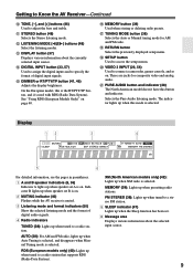
...pages in parentheses. 1 A and B speaker indicators (6, 36) Indicator A lights up when this mode is on . 2 MUTING indicator (46) Flashes while the AV receiver is selected. L LISTENING MODE [ ]/[ ] buttons (48) Select the listening modes. R RETURN button Selects the previously displayed setup menu. There are jacks for AM... (38): Lights up when XM radio is the RT/PTY/TP button, and it's used with RDS (Radio Data System). Getting to Know the AV Receiver-Continued J TONE, [-], and [+] buttons (46) Used to a radio station that supports RDS (Radio Data System). K STEREO button (48) Selects...
...pages in parentheses. 1 A and B speaker indicators (6, 36) Indicator A lights up when this mode is on . 2 MUTING indicator (46) Flashes while the AV receiver is selected. L LISTENING MODE [ ]/[ ] buttons (48) Select the listening modes. R RETURN button Selects the previously displayed setup menu. There are jacks for AM... (38): Lights up when XM radio is the RT/PTY/TP button, and it's used with RDS (Radio Data System). Getting to Know the AV Receiver-Continued J TONE, [-], and [+] buttons (46) Used to a radio station that supports RDS (Radio Data System). K STEREO button (48) Selects...
Owner Manual
Page 10
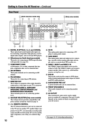
... (see page 3). I REMOTE CONTROL This Remote Interactive jack can be used to supply power to another AV component. The VIDEO 2 inputs can be used to connect another -capable Onkyo com- See pages 16-31 for connecting an AM antenna. D AM ANTENNA These push terminals are for...SPEAKERS A L CENTER SPEAKER R PRE OUT SUB WOOFER FRONT SPEAKERS B L R VOLTAGE SELECTOR AC OUTLET AC 120V 60Hz SWITCHED TOTAL 120W 1A MAX. 120V AV RECEIVER 220-240V 9 JK L M A DIGITAL IN OPTICAL 1, 2, 3, and COAXIAL These optical and coaxial digital audio inputs are for connecting components with an ...
... (see page 3). I REMOTE CONTROL This Remote Interactive jack can be used to supply power to another AV component. The VIDEO 2 inputs can be used to connect another -capable Onkyo com- See pages 16-31 for connecting an AM antenna. D AM ANTENNA These push terminals are for...SPEAKERS A L CENTER SPEAKER R PRE OUT SUB WOOFER FRONT SPEAKERS B L R VOLTAGE SELECTOR AC OUTLET AC 120V 60Hz SWITCHED TOTAL 120W 1A MAX. 120V AV RECEIVER 220-240V 9 JK L M A DIGITAL IN OPTICAL 1, 2, 3, and COAXIAL These optical and coaxial digital audio inputs are for connecting components with an ...
Owner Manual
Page 11
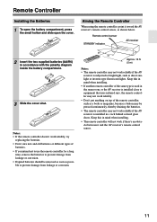
...doesn't work if there's an obstacle between it toward the AV receiver's remote control sensor, as a book or magazine, because a button may not work reliably if the AV receiver is installed in the same room, or the AV receiver is installed close to equipment that uses infrared rays, the ...; The remote controller may be removed as soon as direct sunlight or inverter-type fluorescent lights. Remote control sensor STANDBY indicator AV receiver 2 Insert the two supplied batteries (AA/R6) in mind when installing. • If another remote controller of the remote controller, such...
...doesn't work if there's an obstacle between it toward the AV receiver's remote control sensor, as a book or magazine, because a button may not work reliably if the AV receiver is installed in the same room, or the AV receiver is installed close to equipment that uses infrared rays, the ...; The remote controller may be removed as soon as direct sunlight or inverter-type fluorescent lights. Remote control sensor STANDBY indicator AV receiver 2 Insert the two supplied batteries (AA/R6) in mind when installing. • If another remote controller of the remote controller, such...
Owner Manual
Page 12
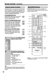
... HDD RC-647M P Q Buttons 1, 2, 3, and 4 are selected by using the six REMOTE MODE buttons. ■ RECEIVER/TAPE Mode In RECEIVER/TAPE mode, you can control RECEIVER the AV receiver and an Onkyo cassette TAPE recorder connected via . 1 2 3 1 4 2 5 36 7 4 8 9 J ON/STANDBY REMOTE MODE RECEIVER DVD TAPE INPUT SELECTOR 1 2 3 V1 V2 V3 M D/CDR C D HDD 4 5 6 TV MULTI CH DVD 7 8 9 VCR...
... HDD RC-647M P Q Buttons 1, 2, 3, and 4 are selected by using the six REMOTE MODE buttons. ■ RECEIVER/TAPE Mode In RECEIVER/TAPE mode, you can control RECEIVER the AV receiver and an Onkyo cassette TAPE recorder connected via . 1 2 3 1 4 2 5 36 7 4 8 9 J ON/STANDBY REMOTE MODE RECEIVER DVD TAPE INPUT SELECTOR 1 2 3 V1 V2 V3 M D/CDR C D HDD 4 5 6 TV MULTI CH DVD 7 8 9 VCR...

Owner Manual
Page 13
...N MUTING button (46) Mutes or unmutes the AV receiver. O SETUP button Used to adjust the level of the currently selected remote controller mode. The Left and Right [ ]/[ ] buttons are used to select categories. ■ Buttons used to select channels, and the [ENTER] button is used when ... and B on or off. K REMOTE MODE buttons (12) Used to select the input sources. M VOL [ ]/[ ] button (36) Adjusts the volume of the AV receiver regardless of each speaker. Play [ ] button Starts playback. Rewind and FF [ ]/[ ] buttons The Rewind [ ] button starts rewind. C MULTI CH button (37) ...
...N MUTING button (46) Mutes or unmutes the AV receiver. O SETUP button Used to adjust the level of the currently selected remote controller mode. The Left and Right [ ]/[ ] buttons are used to select categories. ■ Buttons used to select channels, and the [ENTER] button is used when ... and B on or off. K REMOTE MODE buttons (12) Used to select the input sources. M VOL [ ]/[ ] button (36) Adjusts the volume of the AV receiver regardless of each speaker. Play [ ] button Starts playback. Rewind and FF [ ]/[ ] buttons The Rewind [ ] button starts rewind. C MULTI CH button (37) ...
Owner Manual
Page 16
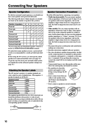
...right Gray Surround back left Brown Surround back right Tan The supplied speaker labels are also color-coded and you must specify which channels you should use the amplifier at high volume levels for a really powerful and solid bass. Doing so may be ...terminals. 16 If you should connect seven speakers and a powered subwoofer. Number of time, the built-in amp protection circuit may damage the AV receiver. • Don't connect a speaker to only negative (-) terminals. Connecting Your Speakers Speaker Configuration For the best surround-sound experience...
...right Gray Surround back left Brown Surround back right Tan The supplied speaker labels are also color-coded and you must specify which channels you should use the amplifier at high volume levels for a really powerful and solid bass. Doing so may be ...terminals. 16 If you should connect seven speakers and a powered subwoofer. Number of time, the built-in amp protection circuit may damage the AV receiver. • Don't connect a speaker to only negative (-) terminals. Connecting Your Speakers Speaker Configuration For the best surround-sound experience...

Owner Manual
Page 17
... SPEAKERS FRONT SPEAKERS A L CENTER SPEAKER R PRE OUT SUB WOOFER FRONT SPEAKERS B L R AV RECEIVER AC OUTLET AC 120V 60Hz SWITCHED TOTAL 120W 1A MAX. Connecting a Powered Subwoofer Using a suitable cable, connect the AV receiver's SUBWOOFER PRE OUT to the input on , speaker set A is unpowered and you 're... back left speaker Surround right speaker Surround left speaker The following illustration shows which speaker should be connected to it to 5.1-channel playback. Fully insert the bare wire, making sure that the terminals are pushed in the center. Screw the terminal tight....
... SPEAKERS FRONT SPEAKERS A L CENTER SPEAKER R PRE OUT SUB WOOFER FRONT SPEAKERS B L R AV RECEIVER AC OUTLET AC 120V 60Hz SWITCHED TOTAL 120W 1A MAX. Connecting a Powered Subwoofer Using a suitable cable, connect the AV receiver's SUBWOOFER PRE OUT to the input on , speaker set A is unpowered and you 're... back left speaker Surround right speaker Surround left speaker The following illustration shows which speaker should be connected to it to 5.1-channel playback. Fully insert the bare wire, making sure that the terminals are pushed in the center. Screw the terminal tight....

Owner Manual
Page 18
... securely and that you don't injure yourself when using it with a commercially available outdoor AM antenna (see page 19). 18 Once your AV receiver is ready for use the tuner. Keep the antenna as far away as shown. (The antenna's wires are gripping the bare wires, ... CENTER SURR BACK R VIDEO 2 VIDEO 1 SUB WOOFER DVD SURROUND SPEAKERS FRONT SPEAKERS A L CENTER SPEAKER R PRE OUT SUB WOOFER FRONT SPEAKERS B L R AV RECEIVER AC OUTLET AC 120V 60Hz SWITCHED TOTAL 120W 1A MAX. If you 'll need to connect commercially available outdoor FM and AM antennas. Connecting Antennas...
... securely and that you don't injure yourself when using it with a commercially available outdoor AM antenna (see page 19). 18 Once your AV receiver is ready for use the tuner. Keep the antenna as far away as shown. (The antenna's wires are gripping the bare wires, ... CENTER SURR BACK R VIDEO 2 VIDEO 1 SUB WOOFER DVD SURROUND SPEAKERS FRONT SPEAKERS A L CENTER SPEAKER R PRE OUT SUB WOOFER FRONT SPEAKERS B L R AV RECEIVER AC OUTLET AC 120V 60Hz SWITCHED TOTAL 120W 1A MAX. If you 'll need to connect commercially available outdoor FM and AM antennas. Connecting Antennas...

Owner Manual
Page 19
... this can sometimes be grounded in accordance with the supplied indoor FM antenna, try a commercially available outdoor FM antenna instead. TV/FM antenna splitter To AV receiver To TV (or VCR) 19 Outdoor antenna AM loop antenna Insulated antenna cable Notes: • Outdoor FM antennas work best when installed horizontally outside , but...
... this can sometimes be grounded in accordance with the supplied indoor FM antenna, try a commercially available outdoor FM antenna instead. TV/FM antenna splitter To AV receiver To TV (or VCR) 19 Outdoor antenna AM loop antenna Insulated antenna cable Notes: • Outdoor FM antennas work best when installed horizontally outside , but...

Owner Manual
Page 20
... offers the best sound quality and allows you to connect right-channel audio inputs and outputs (typically labeled "R"). Connecting Your Components About AV Connections • Before making any AV connections, read the manuals supplied with a 7.1channel analog audio output. Optical Digital Jacks The AV receiver's optical digital jacks have shutter-type covers that open when...
... offers the best sound quality and allows you to connect right-channel audio inputs and outputs (typically labeled "R"). Connecting Your Components About AV Connections • Before making any AV connections, read the manuals supplied with a 7.1channel analog audio output. Optical Digital Jacks The AV receiver's optical digital jacks have shutter-type covers that open when...
Owner Manual
Page 21
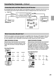
...TV, projector, etc. Use the following sections as the input will depend on the AV receiver. : Signal Flow Video Video Audio Audio DVD player, etc. Output Optical Coaxial IN AV Receiver Optical Coaxial Analog Analog Multichannel Multichannel TV, projector, etc. The format you choose will... recorder, etc. Video Connection Formats Audio Connection Formats When choosing a connection format, bear in mind that the AV receiver doesn't convert between formats, so only outputs of AV equipment. For video components, such as a DVD player, you must also connect it to the analog CD...
...TV, projector, etc. Use the following sections as the input will depend on the AV receiver. : Signal Flow Video Video Audio Audio DVD player, etc. Output Optical Coaxial IN AV Receiver Optical Coaxial Analog Analog Multichannel Multichannel TV, projector, etc. The format you choose will... recorder, etc. Video Connection Formats Audio Connection Formats When choosing a connection format, bear in mind that the AV receiver doesn't convert between formats, so only outputs of AV equipment. For video components, such as a DVD player, you must also connect it to the analog CD...

Owner Manual
Page 22
... speaker set B. • To enjoy Dolby Digital and DTS, use connection b or c . (For recording, use its tuner to listen to the AV receiver and use a and b , or a and c .) Connection A B C a b c AV receiver COMPONENT VIDEO OUT MONITOR OUT S MONITOR OUT V VIDEO 2 IN L/R DIGITAL IN COAXIAL DIGITAL IN OPTICAL 2 Signal flow TV Component video input... TV ( A , B , or C ), and then make the connection. • With connection a , you can listen to and record audio from your VCR or cable or satellite receiver to TV programs through the AV receiver (see page 33) TV, projector, etc.
... speaker set B. • To enjoy Dolby Digital and DTS, use connection b or c . (For recording, use its tuner to listen to the AV receiver and use a and b , or a and c .) Connection A B C a b c AV receiver COMPONENT VIDEO OUT MONITOR OUT S MONITOR OUT V VIDEO 2 IN L/R DIGITAL IN COAXIAL DIGITAL IN OPTICAL 2 Signal flow TV Component video input... TV ( A , B , or C ), and then make the connection. • With connection a , you can listen to and record audio from your VCR or cable or satellite receiver to TV programs through the AV receiver (see page 33) TV, projector, etc.

Owner Manual
Page 23
You must be sure to and record audio from a DVD and listen via the same type of connection. Connection A B C a b c AV receiver COMPONENT VIDEO DVD IN DVD IN S DVD IN V DVD IN FRONT DIGITAL IN COAXIAL DIGITAL IN OPTICAL 1 Signal flow DVD player Component video...B L R COAXIAL OUT OPTICAL OUT Y PB PR COMPONENT VIDEO OUT L R AUDIO OUT S VIDEO OUT VIDEO OUT Connect one or the other Connection c must connect the AV receiver to your TV via speaker set B. • To enjoy Dolby Digital and DTS, use connection b or c . (For recording, use the main left and right outputs...
You must be sure to and record audio from a DVD and listen via the same type of connection. Connection A B C a b c AV receiver COMPONENT VIDEO DVD IN DVD IN S DVD IN V DVD IN FRONT DIGITAL IN COAXIAL DIGITAL IN OPTICAL 1 Signal flow DVD player Component video...B L R COAXIAL OUT OPTICAL OUT Y PB PR COMPONENT VIDEO OUT L R AUDIO OUT S VIDEO OUT VIDEO OUT Connect one or the other Connection c must connect the AV receiver to your TV via speaker set B. • To enjoy Dolby Digital and DTS, use connection b or c . (For recording, use the main left and right outputs...

Owner Manual
Page 24
... analog audio cable, or several normal audio cables, to connect the AV receiver's DVD IN FRONT L/R, CENTER, SURROUND L/R, SURR BACK L/R, and SUBWOOFER jacks to the 7.1-channel analog audio output on your DVD player has a 5.1-channel analog audio output, don't connect anything to the AV receiver's multichannel DVD input. Connecting Your Components-Continued Hooking Up the Multichannel...
... analog audio cable, or several normal audio cables, to connect the AV receiver's DVD IN FRONT L/R, CENTER, SURROUND L/R, SURR BACK L/R, and SUBWOOFER jacks to the 7.1-channel analog audio output on your DVD player has a 5.1-channel analog audio output, don't connect anything to the AV receiver's multichannel DVD input. Connecting Your Components-Continued Hooking Up the Multichannel...


