Owner Manual
Page 5
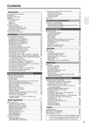
...AV receiver 18 Connecting Your Speakers 18 Bi-amping the Front Speakers A 23 Bridging the Front Speakers A 24 Bi-amping the Front Speakers B 25 Bridging the Front Speakers B 26 Connecting Antenna 27 About AV Connections 29 Connecting Components with HDMI... AV Receiver 120 Listening to Internet Radio 121 Playing Music Files on a Server 122 Network ... Control Codes 141 Remote Control Codes for Onkyo Components Connected via V 142 Resetting REMOTE ... 154 Specifications (TX-NR3007 160 Specifications (TX-NR5007 161 Video Resolution Chart 162 * To reset the AV receiver to its factory...
...AV receiver 18 Connecting Your Speakers 18 Bi-amping the Front Speakers A 23 Bridging the Front Speakers A 24 Bi-amping the Front Speakers B 25 Bridging the Front Speakers B 26 Connecting Antenna 27 About AV Connections 29 Connecting Components with HDMI... AV Receiver 120 Listening to Internet Radio 121 Playing Music Files on a Server 122 Network ... Control Codes 141 Remote Control Codes for Onkyo Components Connected via V 142 Resetting REMOTE ... 154 Specifications (TX-NR3007 160 Specifications (TX-NR5007 161 Video Resolution Chart 162 * To reset the AV receiver to its factory...

Owner Manual
Page 6
play setup) RI-Compatible Learning Remote with permission. *2. THX may vary depending on the region. • Network Capability for Streaming Audio Files • Bi-Amping and BTL Capability • USB Port for a USB Mass ...Neural Surround Decoding*10 • DSD Direct Connections • 7 HDMI*5 Inputs and 2 Outputs (TX-NR3007) • 8 HDMI*5 Inputs and 2 Outputs (TX-NR5007) • Onkyo for System Control • 6 Digital Inputs (3 Optical/3 Coaxial) (TX-NR3007) • 7 Digital Inputs (4 Optical/3 Coaxial) (TX-NR5007) • Universal Port for UP-A1 (Dock for Gaming; ...
play setup) RI-Compatible Learning Remote with permission. *2. THX may vary depending on the region. • Network Capability for Streaming Audio Files • Bi-Amping and BTL Capability • USB Port for a USB Mass ...Neural Surround Decoding*10 • DSD Direct Connections • 7 HDMI*5 Inputs and 2 Outputs (TX-NR3007) • 8 HDMI*5 Inputs and 2 Outputs (TX-NR5007) • Onkyo for System Control • 6 Digital Inputs (3 Optical/3 Coaxial) (TX-NR3007) • 7 Digital Inputs (4 Optical/3 Coaxial) (TX-NR5007) • Universal Port for UP-A1 (Dock for Gaming; ...

Owner Manual
Page 10
...selected can be used by the current listening mode. B Speaker/channel indicators Indicate the speaker channels used to OFF, the AV receiver is the main power switch. G NETWORK indicator (121) Lights when the Net input selector is selected. Audyssey (61, 98): Flashes during Audyssey MultEQ® ...is enabled. M N O PQ F Listening mode and format indicators (81) Show the selected listening mode and audio input signal format. AUX 1 INPUT HDMI (31) Used to adjust the tone (bass and treble) for the main room and the volume, tone and balance for composite video, analog audio,...
...selected can be used by the current listening mode. B Speaker/channel indicators Indicate the speaker channels used to OFF, the AV receiver is the main power switch. G NETWORK indicator (121) Lights when the Net input selector is selected. Audyssey (61, 98): Flashes during Audyssey MultEQ® ...is enabled. M N O PQ F Listening mode and format indicators (81) Show the selected listening mode and audio input signal format. AUX 1 INPUT HDMI (31) Used to adjust the tone (bass and treble) for the main room and the volume, tone and balance for composite video, analog audio,...

Owner Manual
Page 11
... tuned to a radio station that 's selected as the audio source: HDMI, ANALOG, or DIGITAL. AUTO (73): Lights when Auto Tuning mode is for connecting components with the Universal Port option such as CD and DVD/BD players. Rear Panel (TX-NR5007) * North American models BCDE F G HI JK L M NO ...TX-NR5007) These optical digital audio inputs are plugged into the PHONES jack. I SLEEP indicator (69) Lights when the Sleep function has been set to other components. C IR IN/OUT A commercially available IR receiver can be connected to the IR IN jack, allowing you to control the AV receiver...
... tuned to a radio station that 's selected as the audio source: HDMI, ANALOG, or DIGITAL. AUTO (73): Lights when Auto Tuning mode is for connecting components with the Universal Port option such as CD and DVD/BD players. Rear Panel (TX-NR5007) * North American models BCDE F G HI JK L M NO ...TX-NR5007) These optical digital audio inputs are plugged into the PHONES jack. I SLEEP indicator (69) Lights when the Sleep function has been set to other components. C IR IN/OUT A commercially available IR receiver can be connected to the IR IN jack, allowing you to control the AV receiver...

Owner Manual
Page 12
See "Digital Audio Input Setup" on another Onkyo AV component. H V REMOTE CONTROL This V (Remote Interactive) jack can connect...assign each one to an input selector to your setup. When Zone 3 is for connecting the AV receiver to suit your Ethernet network (e.g., router or switch) for playing music files on a component in Zone 2. Input and output ...(TX-NR5007) A USB mass storage device, such as a USB flash drive or MP3 player, containing music files can be plugged in Zone 3. See "HDMI Input Setup" on a component in here and the music selected can connect a cable/satellite receiver,...
See "Digital Audio Input Setup" on another Onkyo AV component. H V REMOTE CONTROL This V (Remote Interactive) jack can connect...assign each one to an input selector to your setup. When Zone 3 is for connecting the AV receiver to suit your Ethernet network (e.g., router or switch) for playing music files on a component in Zone 2. Input and output ...(TX-NR5007) A USB mass storage device, such as a USB flash drive or MP3 player, containing music files can be plugged in Zone 3. See "HDMI Input Setup" on a component in here and the music selected can connect a cable/satellite receiver,...

Owner Manual
Page 14
...• If you want to operate an Onkyo component without V connection, point the remote controller at the other component to use it. • When you intend not to use the remote controller, point it at the AV receiver's remote con- light or inverter-type fluorescent... reliably if the AV receiver is subjected to operate an Onkyo component with the polarity diagram inside the battery compartment. 3 Replace the cover and push it and the AV receiver's remote con- nent connected via HDMI (pages 143 and 144), point the remote controller at the AV receiver's remote control sensor...
...• If you want to operate an Onkyo component without V connection, point the remote controller at the other component to use it. • When you intend not to use the remote controller, point it at the AV receiver's remote con- light or inverter-type fluorescent... reliably if the AV receiver is subjected to operate an Onkyo component with the polarity diagram inside the battery compartment. 3 Replace the cover and push it and the AV receiver's remote con- nent connected via HDMI (pages 143 and 144), point the remote controller at the AV receiver's remote control sensor...
Owner Manual
Page 29
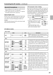
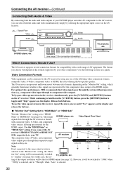
... video cables away from power cords and speaker cables. Connecting the AV receiver-Continued About AV Connections • Before making any AV connections, read the manuals supplied with a 7.1channel analog audio output. Push plugs in all AV connections. Use red plugs to enjoy surround sound (e.g., Dolby Digital,... (RCA) Y PB/CB PR/CR Multichannel analog audio cable (RCA) The AV receiver does not support SCART plugs. Jack HDMI V OPTICAL L R Description HDMI connections can be found on TVs, VCRs, and other AV components. • Don't connect the power cord until you to connect left...
... video cables away from power cords and speaker cables. Connecting the AV receiver-Continued About AV Connections • Before making any AV connections, read the manuals supplied with a 7.1channel analog audio output. Push plugs in all AV connections. Use red plugs to enjoy surround sound (e.g., Dolby Digital,... (RCA) Y PB/CB PR/CR Multichannel analog audio cable (RCA) The AV receiver does not support SCART plugs. Jack HDMI V OPTICAL L R Description HDMI connections can be found on TVs, VCRs, and other AV components. • Don't connect the power cord until you to connect left...

Owner Manual
Page 30
... (Consumer Electronics Control), which stands for Remote Interactive over HDMI and is connected, the linked operations are not guaranteed. • The control does not support HDMI OUT SUB. The AV receiver's HDMI interface is based on Onkyo components. DVD/BD recorder is to address the industry's... more than the above audio formats. ■ Onkyo for System Control , which allows system control over HDMI, is up to four. • Do not connect the AV receiver to the other AV receiver /AV amplifier via HDMI must also support HDMI output of the above -mentioned is part of ...
... (Consumer Electronics Control), which stands for Remote Interactive over HDMI and is connected, the linked operations are not guaranteed. • The control does not support HDMI OUT SUB. The AV receiver's HDMI interface is based on Onkyo components. DVD/BD recorder is to address the industry's... more than the above audio formats. ■ Onkyo for System Control , which allows system control over HDMI, is up to four. • Do not connect the AV receiver to the other AV receiver /AV amplifier via HDMI must also support HDMI output of the above -mentioned is part of ...
Owner Manual
Page 31
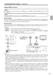
... "On" (see page 54). ■ Video Signals Digital video signals received by the HDMI IN jacks are muted. Connecting the AV receiver-Continued Making HDMI Connections Step 1: Use HDMI cables to connect the AV receiver's HDMI jacks to your DVD/BD player's HDMI audio output setting to PCM. HDMI OUT HDMI IN TV DVD/BD player HD camcorder, etc Notes: • The...
... "On" (see page 54). ■ Video Signals Digital video signals received by the HDMI IN jacks are muted. Connecting the AV receiver-Continued Making HDMI Connections Step 1: Use HDMI cables to connect the AV receiver's HDMI jacks to your DVD/BD player's HDMI audio output setting to PCM. HDMI OUT HDMI IN TV DVD/BD player HD camcorder, etc Notes: • The...
Owner Manual
Page 32
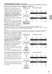
... component video sources all being upconverted for the component video output or the HDMI output. The format you connect the AV Composite S-Video Component IN HDMI receiver's HDMI OUT MAIN or HDMI OUT SUB, respectively, to "HDMI Main" or "HDMI Sub" (see page 52). While continuing to hold down the [VCR/..." appears on the display and release the buttons. ■ "Monitor Out" Setting Set to "HDMI Main" or "HDMI Sub" With the "Monitor Out" setting set to your TV. AV receiver The composite video, S-Video, and component video outputs pass through to the same output you can...
... component video sources all being upconverted for the component video output or the HDMI output. The format you connect the AV Composite S-Video Component IN HDMI receiver's HDMI OUT MAIN or HDMI OUT SUB, respectively, to "HDMI Main" or "HDMI Sub" (see page 52). While continuing to hold down the [VCR/..." appears on the display and release the buttons. ■ "Monitor Out" Setting Set to "HDMI Main" or "HDMI Sub" With the "Monitor Out" setting set to your TV. AV receiver The composite video, S-Video, and component video outputs pass through to the same output you can...
Owner Manual
Page 33
... signals as shown here, with composite video, S-Video, and component video sources all being upconverted Composite S-Video Component HDMI for "HDMI Main". Connecting the AV receiver-Continued ■ "Monitor Out" Setting Set to "Both", "Both(Main)" or "Both(Sub)" With the "Monitor...■ "Monitor Out" Setting Set to "Analog" With the "Monitor Out" setting set to composite video. AV receiver Composite MONITOR OUT S-Video Component HDMI The composite video, S-Video, and component video outputs pass through their respective input signals as they are not output...
... signals as shown here, with composite video, S-Video, and component video sources all being upconverted Composite S-Video Component HDMI for "HDMI Main". Connecting the AV receiver-Continued ■ "Monitor Out" Setting Set to "Both", "Both(Main)" or "Both(Sub)" With the "Monitor...■ "Monitor Out" Setting Set to "Analog" With the "Monitor Out" setting set to composite video. AV receiver Composite MONITOR OUT S-Video Component HDMI The composite video, S-Video, and component video outputs pass through their respective input signals as they are not output...
Owner Manual
Page 34
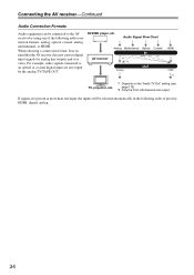
...bear in the following order of the following audio connection formats: analog, optical, coaxial, analog multichannel, or HDMI. Audio Signal Flow Chart Analog Multichannel Optical Coaxial AV receiver Analog HDMI HDMI *1 TV, projector, etc. *1 Depends on the "Audio TV Out" setting (see page 113). *2... L/R channels are not output by using any of priority: HDMI, digital, analog. 34 Connecting the AV receiver-Continued Audio Connection Formats Audio equipment can be selected automatically in mind that the AV receiver does not convert digital input signals for analog line outputs and...
...bear in the following order of the following audio connection formats: analog, optical, coaxial, analog multichannel, or HDMI. Audio Signal Flow Chart Analog Multichannel Optical Coaxial AV receiver Analog HDMI HDMI *1 TV, projector, etc. *1 Depends on the "Audio TV Out" setting (see page 113). *2... L/R channels are not output by using any of priority: HDMI, digital, analog. 34 Connecting the AV receiver-Continued Audio Connection Formats Audio equipment can be selected automatically in mind that the AV receiver does not convert digital input signals for analog line outputs and...

Owner Manual
Page 35
... OPTICAL IN 2 (TV/TAPE) (TX-NR5007) Signal flow ⇐ TV, projector, etc. B (TX-NR3007) When you use connection b , you need to and record audio from your TV ( a , b , or c ), and then make the connection. Connecting the AV receiver-Continued Connecting a TV or Projector See "Connecting Components with HDMI" on page 30 for HDMI connection information. Component video input...
... OPTICAL IN 2 (TV/TAPE) (TX-NR5007) Signal flow ⇐ TV, projector, etc. B (TX-NR3007) When you use connection b , you need to and record audio from your TV ( a , b , or c ), and then make the connection. Connecting the AV receiver-Continued Connecting a TV or Projector See "Connecting Components with HDMI" on page 30 for HDMI connection information. Component video input...
Owner Manual
Page 36
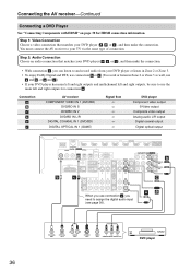
... c .) • If your DVD player ( a , b , or c ), and then make the connection. Connecting the AV receiver-Continued Connecting a DVD Player See "Connecting Components with HDMI" on page 30 for connection a . Step 1: Video Connection Choose a video connection that matches your DVD player has main left ...and right outputs and multichannel left and right outputs for HDMI connection information. Connection A B C a b c AV receiver COMPONENT VIDEO IN 1 (DVD/BD) DVD/BD IN S DVD/BD IN V DVD/BD IN L/R DIGITAL COAXIAL IN ...
... c .) • If your DVD player ( a , b , or c ), and then make the connection. Connecting the AV receiver-Continued Connecting a DVD Player See "Connecting Components with HDMI" on page 30 for connection a . Step 1: Video Connection Choose a video connection that matches your DVD player has main left ...and right outputs and multichannel left and right outputs for HDMI connection information. Connection A B C a b c AV receiver COMPONENT VIDEO IN 1 (DVD/BD) DVD/BD IN S DVD/BD IN V DVD/BD IN L/R DIGITAL COAXIAL IN ...
Owner Manual
Page 48
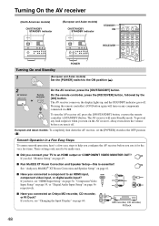
...down the volume before you did, "Monitor Setup" on , the display lights up, and the STANDBY indicator goes off. If you connected an Onkyo MD recorder, CD recorder, or RI Dock? Pressing the remote controller's [ON] button again will enter Standby mode. These settings only need to...and Standby POWER 1 (European and Asian models) Set the [POWER] switch to the ON position ( ). 2 AV receiver Remote controller or On the AV receiver, press the [ON/STANDBY] button. If you have, see "HDMI Input Setup" on page 54, "Component Video Input Setup" on page 55, or "Digital Audio Input Setup" ...
...down the volume before you did, "Monitor Setup" on , the display lights up, and the STANDBY indicator goes off. If you connected an Onkyo MD recorder, CD recorder, or RI Dock? Pressing the remote controller's [ON] button again will enter Standby mode. These settings only need to...and Standby POWER 1 (European and Asian models) Set the [POWER] switch to the ON position ( ). 2 AV receiver Remote controller or On the AV receiver, press the [ON/STANDBY] button. If you have, see "HDMI Input Setup" on page 54, "Component Video Input Setup" on page 55, or "Digital Audio Input Setup" ...

Owner Manual
Page 49
... Time Setup This section explains the settings that you need to make before using the AV receiver for the HDMI outputs and COMPONENT VIDEO MONITOR OUT and have the onscreen setup menu output through the HDMI output or through an analog output. If you connect your TV to match the resolution...select whether or not to have the video sources' images output through the HDMI output, as well as whether to have the AV receiver upconvert the picture resolution as necessary to the COMPONENT VIDEO MONITOR OUT (not the HDMI output), "Monitor Out" setting is automatically set so that the onscreen ...
... Time Setup This section explains the settings that you need to make before using the AV receiver for the HDMI outputs and COMPONENT VIDEO MONITOR OUT and have the onscreen setup menu output through the HDMI output or through an analog output. If you connect your TV to match the resolution...select whether or not to have the video sources' images output through the HDMI output, as well as whether to have the AV receiver upconvert the picture resolution as necessary to the COMPONENT VIDEO MONITOR OUT (not the HDMI output), "Monitor Out" setting is automatically set so that the onscreen ...

Owner Manual
Page 52
...TVs are connected to the HDMI OUT MAIN and HDMI OUT SUB. Notes: • If not connected to the same output you have the AV receiver upconvert the picture resolution as necessary to match the resolution supported by only the HDMI outputs. HDMI Input 3. Digital Audio Input ...5. Monitor Out Monitor Out Resolution Brightness Contrast Hue Saturation HDMI Main Through 0 0 0 0 52 Use the ...
...TVs are connected to the HDMI OUT MAIN and HDMI OUT SUB. Notes: • If not connected to the same output you have the AV receiver upconvert the picture resolution as necessary to match the resolution supported by only the HDMI outputs. HDMI Input 3. Digital Audio Input ...5. Monitor Out Monitor Out Resolution Brightness Contrast Hue Saturation HDMI Main Through 0 0 0 0 52 Use the ...

Owner Manual
Page 54
... the video source based on page 56. • The TUNER input selector cannot be unable to assign HDMI IN to input selector. • "AUX 1" is selected on the AV receiver by using its [SETUP] button, arrow buttons, and [ENTER] button. lowed by selecting the option. If the main ... an input selector, and use the Left and Right [F]/ [S] buttons to select: HDMI1, HDMI2, HDMI3, HDMI4, HDMI5, HDMI6, HDMI7 (TX-NR5007): Select the HDMI IN to which the video component has been connected Output composite video, S-Video, and component video sources from the front panel terminals. Component Video...
... the video source based on page 56. • The TUNER input selector cannot be unable to assign HDMI IN to input selector. • "AUX 1" is selected on the AV receiver by using its [SETUP] button, arrow buttons, and [ENTER] button. lowed by selecting the option. If the main ... an input selector, and use the Left and Right [F]/ [S] buttons to select: HDMI1, HDMI2, HDMI3, HDMI4, HDMI5, HDMI6, HDMI7 (TX-NR5007): Select the HDMI IN to which the video component has been connected Output composite video, S-Video, and component video sources from the front panel terminals. Component Video...
Owner Manual
Page 55
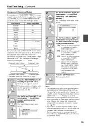
...a COMPONENT VIDEO IN, you should assign it to an input selector. The main menu appears onscreen. The "Input/Output Assign" menu appears. 1. HDMI Input 3. NENT VIDEO IN 2. Notes: • For composite video and S-Video upconversion for the COMPONENT VIDEO MONITOR OUT, the "Monitor Out" ... Input DVD/BD VCR/DVR CBL/SAT GAME AUX 1 IN1 - - - - NENT VIDEO IN 3. - - - - -: Select if you can set the AV receiver so that seated iPod) to the AV receiver with a component video cable, you are upconverted* and output by the [SETUP] button. lowed by the COMPONENT VIDEO MONITOR OUT*1.
...a COMPONENT VIDEO IN, you should assign it to an input selector. The main menu appears onscreen. The "Input/Output Assign" menu appears. 1. HDMI Input 3. NENT VIDEO IN 2. Notes: • For composite video and S-Video upconversion for the COMPONENT VIDEO MONITOR OUT, the "Monitor Out" ... Input DVD/BD VCR/DVR CBL/SAT GAME AUX 1 IN1 - - - - NENT VIDEO IN 3. - - - - -: Select if you can set the AV receiver so that seated iPod) to the AV receiver with a component video cable, you are upconverted* and output by the [SETUP] button. lowed by the COMPONENT VIDEO MONITOR OUT*1.

Owner Manual
Page 56
... [S] buttons to select "COAX1", "COAX2", "COAX3", "OPT1", "OPT2", "OPT3" (TX-NR5007), or "- - - - - (analog)". • When an HDMI IN is selected on page 54, the AV receiver will select audio from HDMI IN as UP-A1 Dock that seated iPod) to the UNIVERSAL PORT jack, you cannot assign... also be changed. Input selector DVD/BD VCR/DVR CBL/SAT GAME AUX 1 AUX 2 TV/TAPE TUNER CD PHONO PORT Default assignment (TX-NR3007) (TX-NR5007) COAX1 COAX1 COAX2 COAX2 COAX3 COAX3 OPT1 OPT1 FRONT (Fixed) FRONT (Fixed) ----- ----- ----- Monitor Out 2. For example, if you ...
... [S] buttons to select "COAX1", "COAX2", "COAX3", "OPT1", "OPT2", "OPT3" (TX-NR5007), or "- - - - - (analog)". • When an HDMI IN is selected on page 54, the AV receiver will select audio from HDMI IN as UP-A1 Dock that seated iPod) to the UNIVERSAL PORT jack, you cannot assign... also be changed. Input selector DVD/BD VCR/DVR CBL/SAT GAME AUX 1 AUX 2 TV/TAPE TUNER CD PHONO PORT Default assignment (TX-NR3007) (TX-NR5007) COAX1 COAX1 COAX2 COAX2 COAX3 COAX3 OPT1 OPT1 FRONT (Fixed) FRONT (Fixed) ----- ----- ----- Monitor Out 2. For example, if you ...


