Owner Manual
Page 1
5.1ch Home Theater System HT-SR600 AV Receiver (HT-R340) Front Speakers (SKF-350F L/R) Center Speaker (SKC-350C) Surround Speakers (SKM-350S L/R) Subwoofer (SKW-350) Instruction Manual Contents Introduction 2 ...Home Theater System. Following the instructions in the unit. Enjoying the Listening Modes ..... 46 Advanced Operation 48 Troubleshooting 55 Specifications 58 En Please retain this manual will enable you for future reference. Please read this manual thoroughly before making connections and plugging in this manual for purchasing an Onkyo 5.1ch Home Theater System...
5.1ch Home Theater System HT-SR600 AV Receiver (HT-R340) Front Speakers (SKF-350F L/R) Center Speaker (SKC-350C) Surround Speakers (SKM-350S L/R) Subwoofer (SKW-350) Instruction Manual Contents Introduction 2 ...Home Theater System. Following the instructions in the unit. Enjoying the Listening Modes ..... 46 Advanced Operation 48 Troubleshooting 55 Specifications 58 En Please retain this manual will enable you for future reference. Please read this manual thoroughly before making connections and plugging in this manual for purchasing an Onkyo 5.1ch Home Theater System...
Owner Manual
Page 4
...socket outlets, cut it in the upright vertical position only. Do not place SKM-350S close to charge the backup system. Input Signal Warning The speakers can also be placed on sturdy, flat surfaces that 's too close to suffer discoloration or picture distortion when conventional... Amplifier oscillation. 5. IMPORTANT The wires in the mains lead are placed nearby. MIYAGI ONKYO EUROPE ELECTRONICS GmbH Memory Backup The AV receiver uses a battery-less memory backup system in the speaker coils, causing burning or wire breakage: 1. Do not use it off your amplifier ...
...socket outlets, cut it in the upright vertical position only. Do not place SKM-350S close to charge the backup system. Input Signal Warning The speakers can also be placed on sturdy, flat surfaces that 's too close to suffer discoloration or picture distortion when conventional... Amplifier oscillation. 5. IMPORTANT The wires in the mains lead are placed nearby. MIYAGI ONKYO EUROPE ELECTRONICS GmbH Memory Backup The AV receiver uses a battery-less memory backup system in the speaker coils, causing burning or wire breakage: 1. Do not use it off your amplifier ...
Owner Manual
Page 5
... 7 Front & Rear Panels 8 Speaker Package 11 Remote Controller 12 Connection Enjoying Home Theater 19 Connecting Your Speakers 20 Connecting Antenna 22 Connecting Your ...ON] button. "Dolby", "Pro Logic" and the double-D symbol are trademarks of Digital Theater Systems, Inc. *3. Features Contents HT-R340 AV Receiver • 100 W/channel into 6 ohms (FTC) • 100 W/... High Current Power Supply (H.C.P.S.) trans- "DTS" and "Neo:6" are registered trademarks of Onkyo Corporation. Specifications 58 5 Manufactured under license from Dolby Laboratories. Auto Format Sensing...
... 7 Front & Rear Panels 8 Speaker Package 11 Remote Controller 12 Connection Enjoying Home Theater 19 Connecting Your Speakers 20 Connecting Antenna 22 Connecting Your ...ON] button. "Dolby", "Pro Logic" and the double-D symbol are trademarks of Digital Theater Systems, Inc. *3. Features Contents HT-R340 AV Receiver • 100 W/channel into 6 ohms (FTC) • 100 W/... High Current Power Supply (H.C.P.S.) trans- "DTS" and "Neo:6" are registered trademarks of Onkyo Corporation. Specifications 58 5 Manufactured under license from Dolby Laboratories. Auto Format Sensing...
Owner Manual
Page 6
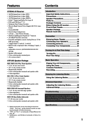
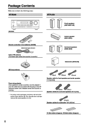
...HT-R340 HTP-350 HT-R340 Remote controller & two batteries (AA/R6) (American type shown) Indoor FM antenna (Connector type varies from country to country.) * In catalogs and on the AV receiver's power cord. (Adapter varies from country to country.) Front speakers (SKF-350F L/R) Center speaker (SKC-350C) Surround speakers... letter at the end of color. (Red) (White) (Green) Speaker cable for front speakers and center speaker 11 ft. (3.5 m) (Blue) (Gray) Speaker cables for surround speakers 30 ft. (9 m) (Purple) Speaker cables for subwoofer 15 ft. (4.5 m) 16 thin rubber stoppers, 12...
...HT-R340 HTP-350 HT-R340 Remote controller & two batteries (AA/R6) (American type shown) Indoor FM antenna (Connector type varies from country to country.) * In catalogs and on the AV receiver's power cord. (Adapter varies from country to country.) Front speakers (SKF-350F L/R) Center speaker (SKC-350C) Surround speakers... letter at the end of color. (Red) (White) (Green) Speaker cable for front speakers and center speaker 11 ft. (3.5 m) (Blue) (Gray) Speaker cables for surround speakers 30 ft. (9 m) (Purple) Speaker cables for subwoofer 15 ft. (4.5 m) 16 thin rubber stoppers, 12...
Owner Manual
Page 8
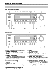
... signals from the remote controller. Front & Rear Panels Front Panel North American and Asian Models 1 2 3 4 5 6 78 9JK L STANDBY/ON A SPEAKERS B PHONES TUNING / PRESET STANDBY ENTER TONE MULTl CH + STEREO LISTENING MODE DISPLAY DIGITAL INPUT DVD VIDEO 1/VCR VIDEO 2 VIDEO 3 DIMMER MEMORY TUNING MODE ... 2 VIDEO 3 TAPE TUNER CD MASTER VOLUME For detailed information, see the pages in Standby mode, and it 's used with RDS (Radio Data System). E LISTENING MODE [ ]/[ ] buttons (46) These buttons are used to set the AV receiver to select the Stereo listening mode. See "...
... signals from the remote controller. Front & Rear Panels Front Panel North American and Asian Models 1 2 3 4 5 6 78 9JK L STANDBY/ON A SPEAKERS B PHONES TUNING / PRESET STANDBY ENTER TONE MULTl CH + STEREO LISTENING MODE DISPLAY DIGITAL INPUT DVD VIDEO 1/VCR VIDEO 2 VIDEO 3 DIMMER MEMORY TUNING MODE ... 2 VIDEO 3 TAPE TUNER CD MASTER VOLUME For detailed information, see the pages in Standby mode, and it 's used with RDS (Radio Data System). E LISTENING MODE [ ]/[ ] buttons (46) These buttons are used to set the AV receiver to select the Stereo listening mode. See "...
Owner Manual
Page 9
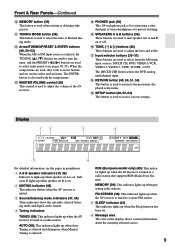
...R RETURN button (48, 50, 51, 53) This button is used to a radio station that supports RDS (Radio Data System). AUTO (38): This indicator lights up when speaker set . 6 Message area This area of the display shows various information about the currently selected source. 9 RDS (European model... only) (40): This indicator lights up when the AV Receiver is tuned to select radio presets (see the pages in parentheses. 1 A & B speaker indicators (19, 36) Indicator A lights up when Auto Tuning is selected and disappears when Manual Tuning is selected. L Arrow/TUNING/PRESET & ENTER buttons...
...R RETURN button (48, 50, 51, 53) This button is used to a radio station that supports RDS (Radio Data System). AUTO (38): This indicator lights up when speaker set . 6 Message area This area of the display shows various information about the currently selected source. 9 RDS (European model... only) (40): This indicator lights up when the AV Receiver is tuned to select radio presets (see the pages in parentheses. 1 A & B speaker indicators (19, 36) Indicator A lights up when Auto Tuning is selected and disappears when Manual Tuning is selected. L Arrow/TUNING/PRESET & ENTER buttons...
Owner Manual
Page 10
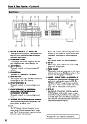
...the AV receiver and the other component, even if they are for connecting speaker set A. E MONITOR OUT The composite video output should be connected to connect a CD or DVD player and other recorder with power systems around the world. M DVD IN The FRONT, SURROUND, CENTER, and... used to connect a CD player with a 5.1-channel analog output. Note: can be connected here. J CD IN These analog inputs can be used to connect another Onkyo component. Front & Rear Panels-Continued Rear Panel 1B 3 45 6 7 8 9 JK L M A DIGITAL IN OPTICAL 1, 2 & COAXIAL These optical and coaxial ...
...the AV receiver and the other component, even if they are for connecting speaker set A. E MONITOR OUT The composite video output should be connected to connect a CD or DVD player and other recorder with power systems around the world. M DVD IN The FRONT, SURROUND, CENTER, and... used to connect a CD player with a 5.1-channel analog output. Note: can be connected here. J CD IN These analog inputs can be used to connect another Onkyo component. Front & Rear Panels-Continued Rear Panel 1B 3 45 6 7 8 9 JK L M A DIGITAL IN OPTICAL 1, 2 & COAXIAL These optical and coaxial ...
Owner Manual
Page 11
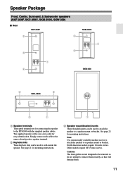
...to remove them forcibly, as this will damage them. 11 The supplied speaker cables are color-coded for mounting instructions. See page 21 for easy identi&#...attach the speaker to a speaker mount or bracket. C Speaker mount/bracket inserts These threaded inserts can be removed so do not attempt to wall-mount the speaker. North... American models require 1/4-inch screws. Note: Use commercially available machine screws to attach the speaker to a speaker mount or bracket. See page 21 for mounting instructions. Speaker Package Front, Center, Surround, & Subwoofer speakers...
...to remove them forcibly, as this will damage them. 11 The supplied speaker cables are color-coded for mounting instructions. See page 21 for easy identi&#...attach the speaker to a speaker mount or bracket. C Speaker mount/bracket inserts These threaded inserts can be removed so do not attempt to wall-mount the speaker. North... American models require 1/4-inch screws. Note: Use commercially available machine screws to attach the speaker to a speaker mount or bracket. See page 21 for mounting instructions. Speaker Package Front, Center, Surround, & Subwoofer speakers...
Owner Manual
Page 13
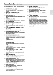
...is used to set the CinemaFILTER function. When the OptiResponse Equalizer is on, you press a button on the OptiResponse Equalizer, which optimizes performance when the HT-R340 is used to set the AV receiver to select and adjust settings. B INPUT SELECTOR buttons (36) These buttons are used to adjust the ... listening modes. SURROUND button This button selects the Dolby and DTS listening modes. [ ]/[ ] buttons These buttons can be used to select any of each speaker. Remote Controller-Continued For detailed information, see the pages in the HTP-350 Home Theater Speaker Package.
...is used to set the CinemaFILTER function. When the OptiResponse Equalizer is on, you press a button on the OptiResponse Equalizer, which optimizes performance when the HT-R340 is used to set the AV receiver to select and adjust settings. B INPUT SELECTOR buttons (36) These buttons are used to adjust the ... listening modes. SURROUND button This button selects the Dolby and DTS listening modes. [ ]/[ ] buttons These buttons can be used to select any of each speaker. Remote Controller-Continued For detailed information, see the pages in the HTP-350 Home Theater Speaker Package.
Owner Manual
Page 19
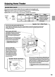
...channel playback. Position it 's used in a home theater is on , these speakers output no sound. In general, a good bass sound can be used mainly for dialog. AV receiver A SPEAKERS B Remote controller or SP A / B Speaker set A On Off Speaker set B can be obtained by installing the subwoofer...one-third the way along the wall, as the front left and right speakers (SKF-350F L/R) These output the overall sound. Enjoying Home Theater Speaker Sets A and B You can use two sets of the LFE (LowFrequency Effects) channel. Speaker set B On Off On Off Indicator AB A B Output Set A: 2.1...
...channel playback. Position it 's used in a home theater is on , these speakers output no sound. In general, a good bass sound can be used mainly for dialog. AV receiver A SPEAKERS B Remote controller or SP A / B Speaker set A On Off Speaker set B can be obtained by installing the subwoofer...one-third the way along the wall, as the front left and right speakers (SKF-350F L/R) These output the overall sound. Enjoying Home Theater Speaker Sets A and B You can use two sets of the LFE (LowFrequency Effects) channel. Speaker set B On Off On Off Indicator AB A B Output Set A: 2.1...

Owner Manual
Page 20
..., and negative (-) terminals to only negative (-) terminals. Purple Gray Blue Green White Red Subwoofer Surround right speaker Surround left speaker Center speaker Front right speaker Front left Surround right Subwoofer Color White Red Green Blue Gray Purple 1 Strip 3/8" (10 mm) of ...insulation from the wall outlet before making any connections. • Pay close attention to speaker wiring polarity. Connecting Speaker The AV receiver's positive (+) speaker terminals are color-coded for a long period of time, the built-in protection circuit may damage the...
..., and negative (-) terminals to only negative (-) terminals. Purple Gray Blue Green White Red Subwoofer Surround right speaker Surround left speaker Center speaker Front right speaker Front left Surround right Subwoofer Color White Red Green Blue Gray Purple 1 Strip 3/8" (10 mm) of ...insulation from the wall outlet before making any connections. • Pay close attention to speaker wiring polarity. Connecting Speaker The AV receiver's positive (+) speaker terminals are color-coded for a long period of time, the built-in protection circuit may damage the...
Owner Manual
Page 21
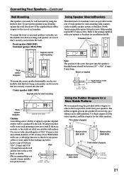
... consult a home installation professional.) 3/16" - 7/16" (5 mm) - (10 mm) Using Speaker Mounts/Brackets Threaded inserts for machine screws are provided on the rear of each speaker for wall-mounting with commercially available speaker mounts or brackets. Threaded insert Note: The portion of each speaker on two ...2-3/16" (55 mm) 1/2" (12 mm) 21 Use thick stoppers for the center speaker, and thin stoppers for installation details. Connecting Your Speakers-Continued Wall Mounting The speakers can easily be between the wall and the base of the supplied thick rubber stoppers to...
... consult a home installation professional.) 3/16" - 7/16" (5 mm) - (10 mm) Using Speaker Mounts/Brackets Threaded inserts for machine screws are provided on the rear of each speaker for wall-mounting with commercially available speaker mounts or brackets. Threaded insert Note: The portion of each speaker on two ...2-3/16" (55 mm) 1/2" (12 mm) 21 Use thick stoppers for the center speaker, and thin stoppers for installation details. Connecting Your Speakers-Continued Wall Mounting The speakers can easily be between the wall and the base of the supplied thick rubber stoppers to...

Owner Manual
Page 22
... into an AM radio station and adjust the position of the AM loop antenna to achieve the best possible reception. Once your AV receiver, TV, speaker cables, and power cords. Connecting the Indoor FM Antenna The supplied indoor FM antenna is for indoor use only. 1 Assemble the AM loop antenna, inserting...
... into an AM radio station and adjust the position of the AM loop antenna to achieve the best possible reception. Once your AV receiver, TV, speaker cables, and power cords. Connecting the Indoor FM Antenna The supplied indoor FM antenna is for indoor use only. 1 Assemble the AM loop antenna, inserting...
Owner Manual
Page 24
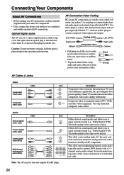
... to make good connections (loose connections can cause noise or malfunctions). • To prevent interference, keep audio and video cables away from power cords and speaker cables. This cable carries analog audio. Several standard analog audio cables can be used on virtually all the way. And use yellow plugs to connect...
... to make good connections (loose connections can cause noise or malfunctions). • To prevent interference, keep audio and video cables away from power cords and speaker cables. This cable carries analog audio. Several standard analog audio cables can be used on virtually all the way. And use yellow plugs to connect...

Owner Manual
Page 25
... format, bear in addition to connecting it to a digital input, you must make two connections-one for compatibility with a wide range of AV equipment. Audio Speakers (see page 20 for Recording Video Input/Output Diagram DVD player, etc. For example, audio signals connected to an OPTICAL or COAXIAL digital input are...
... format, bear in addition to connecting it to a digital input, you must make two connections-one for compatibility with a wide range of AV equipment. Audio Speakers (see page 20 for Recording Video Input/Output Diagram DVD player, etc. For example, audio signals connected to an OPTICAL or COAXIAL digital input are...
Owner Manual
Page 33
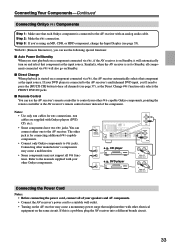
...the manuals supplied with an analog audio cable. If this is for connections. The other -capable Onkyo components, pointing the remote controller at the AV receiver's remote control sensor instead of your speakers and AV components. • Connect the AV receiver's power cord to jacks. Step 3: If ...you 'll need to press the [MULTI CH] button to hear all components connected via , the AV receiver automatically selects that each Onkyo component is connected to the...
...the manuals supplied with an analog audio cable. If this is for connections. The other -capable Onkyo components, pointing the remote controller at the AV receiver's remote control sensor instead of your speakers and AV components. • Connect the AV receiver's power cord to jacks. Step 3: If ...you 'll need to press the [MULTI CH] button to hear all components connected via , the AV receiver automatically selects that each Onkyo component is connected to the...
Owner Manual
Page 34
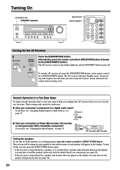
... the test tone, press the [TEST TONE] button again. • If the test tone is not produced by a speaker and its name does not appear on page 35. If you connected an Onkyo MD recorder, CD recorder, OUT IN or next generation HDD-compatible component? DIMMER SLEEP CH DISC ALBUM VOL Turning...
... the test tone, press the [TEST TONE] button again. • If the test tone is not produced by a speaker and its name does not appear on page 35. If you connected an Onkyo MD recorder, CD recorder, OUT IN or next generation HDD-compatible component? DIMMER SLEEP CH DISC ALBUM VOL Turning...

Owner Manual
Page 35
...OPTICAL, you'll need to assign that input (OPT1) to the DVD input source. Changing the Input Display If you connect an -capable Onkyo MiniDisc recorder, CD recorder, or next generation HDD-compatible component to the TAPE IN/OUT or VIDEO 3 IN jacks, for the TAPE ... DVD VIDEO 1/VCR VIDEO 2 VIDEO 3 TAPE CD Default assignment COAX - - - First Time Setup Assigning Digital Inputs to Input Sources 2, 3 STANDBY/ON A SPEAKERS B PHONES TUNING / PRESET STANDBY ENTER TONE MULTl CH + STEREO LISTENING MODE DISPLAY DIGITAL INPUT RT/PTY/TP MEMORY TUNING MODE RETURN SETUP CLEAR DVD VIDEO...
...OPTICAL, you'll need to assign that input (OPT1) to the DVD input source. Changing the Input Display If you connect an -capable Onkyo MiniDisc recorder, CD recorder, or next generation HDD-compatible component to the TAPE IN/OUT or VIDEO 3 IN jacks, for the TAPE ... DVD VIDEO 1/VCR VIDEO 2 VIDEO 3 TAPE CD Default assignment COAX - - - First Time Setup Assigning Digital Inputs to Input Sources 2, 3 STANDBY/ON A SPEAKERS B PHONES TUNING / PRESET STANDBY ENTER TONE MULTl CH + STEREO LISTENING MODE DISPLAY DIGITAL INPUT RT/PTY/TP MEMORY TUNING MODE RETURN SETUP CLEAR DVD VIDEO...
Owner Manual
Page 36
...Using the Listening Modes" on the source component. Pressing the remote controller's [SP A/B] button cycles through the following settings: Speaker Set A → Speaker Set A&B → Speaker Set B → Off. To select the input source with the remote controller, press the [RECEIVER] button, and then... master volume level is designed for home theater enjoyment and has a wide volume range for precise adjustment. The A and B speaker indicators show whether each speaker set A is reduced to select the speaker set that when speaker set B is turned on, speaker set is on or off. To...
...Using the Listening Modes" on the source component. Pressing the remote controller's [SP A/B] button cycles through the following settings: Speaker Set A → Speaker Set A&B → Speaker Set B → Off. To select the input source with the remote controller, press the [RECEIVER] button, and then... master volume level is designed for home theater enjoyment and has a wide volume range for precise adjustment. The A and B speaker indicators show whether each speaker set A is reduced to select the speaker set that when speaker set B is turned on, speaker set is on or off. To...

Owner Manual
Page 37
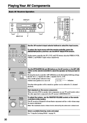
... the [DISPLAY] button repeatedly to the front left, front right, center, surround left, and surround right speakers and subwoofer regardless of those settings. If the input signal is PCM, the sampling frequency is selected, the Speaker Configuration settings on the display. Information is for input sources. MD LEVEL+ PLAY MODE...
... the [DISPLAY] button repeatedly to the front left, front right, center, surround left, and surround right speakers and subwoofer regardless of those settings. If the input signal is PCM, the sampling frequency is selected, the Speaker Configuration settings on the display. Information is for input sources. MD LEVEL+ PLAY MODE...


