

English Manual
Page 1
Write the serial number in this manual before using this equipment. As a manufacturer, we are missing or damaged parts, please contact the establishment where you purchased this manual for future reference. If you have questions, or if there are committed to providing complete customer satisfaction. Save this product. Serial Number Decal (Under Seat) QUESTIONS? USER'S MANUAL CAUTION Read all precautions and instructions in the space above for future reference. NTPRSY3415.0 Serial No. Model No.
Write the serial number in this manual before using this equipment. As a manufacturer, we are missing or damaged parts, please contact the establishment where you purchased this manual for future reference. If you have questions, or if there are committed to providing complete customer satisfaction. Save this product. Serial Number Decal (Under Seat) QUESTIONS? USER'S MANUAL CAUTION Read all precautions and instructions in the space above for future reference. NTPRSY3415.0 Serial No. Model No.

English Manual
Page 2
... the back cover to order a free replacement decal. Apply the decal in the center of ICON IP, Inc. 2 TABLE OF CONTENTS WARNING DECAL PLACEMENT 2 IMPORTANT PRECAUTIONS 3 BEFORE YOU BEGIN 4 ASSEMBLY 5 ADJUSTMENTS 14 CABLE DIAGRAM 17 WEIGHT RESISTANCE CHART 17 EXERCISE GUIDELINES 18 ORDERING REPLACEMENT PARTS Back Cover LIMITED WARRANTY Back Cover Note: A PART IDENTIFICATION CHART and a PART LIST/EXPLODED DRAWING is attached in the location shown. Remove the PART IDENTIFICATION CHART and PART LIST/EXPLODED DRAWING before beginning assembly. NordicTrack is...
... the back cover to order a free replacement decal. Apply the decal in the center of ICON IP, Inc. 2 TABLE OF CONTENTS WARNING DECAL PLACEMENT 2 IMPORTANT PRECAUTIONS 3 BEFORE YOU BEGIN 4 ASSEMBLY 5 ADJUSTMENTS 14 CABLE DIAGRAM 17 WEIGHT RESISTANCE CHART 17 EXERCISE GUIDELINES 18 ORDERING REPLACEMENT PARTS Back Cover LIMITED WARRANTY Back Cover Note: A PART IDENTIFICATION CHART and a PART LIST/EXPLODED DRAWING is attached in the location shown. Remove the PART IDENTIFICATION CHART and PART LIST/EXPLODED DRAWING before beginning assembly. NordicTrack is...

English Manual
Page 3
... the resistance. 13. Never release the ankle strap, leg lever, squat bar, leg press, curl bar, or handles while weights are on a level surface, with dumbbells or any worn parts immediately. 6. WARNING: Before beginning this manual. 2. Always wear athletic shoes for home use the weight system with great force. 15. Read all instructions in any time while exercising, stop immediately and make sure that the cables remain...
... the resistance. 13. Never release the ankle strap, leg lever, squat bar, leg press, curl bar, or handles while weights are on a level surface, with dumbbells or any worn parts immediately. 6. WARNING: Before beginning this manual. 2. Always wear athletic shoes for home use the weight system with great force. 15. Read all instructions in any time while exercising, stop immediately and make sure that the cables remain...

English Manual
Page 4
... this manual). The model number is to the weight system (see the front cover of the body. Before reading further, please review the drawing below and familiarize yourself with the parts that are determined relative to provide the product model number and serial number. The serial number can be prepared to a person sitting on the drawings in . / 239 cm VKR Frame Shroud Weight Stack Swivel Arm Weight Pin...
... this manual). The model number is to the weight system (see the front cover of the body. Before reading further, please review the drawing below and familiarize yourself with the parts that are determined relative to provide the product model number and serial number. The serial number can be prepared to a person sitting on the drawings in . / 239 cm VKR Frame Shroud Weight Stack Swivel Arm Weight Pin...

English Manual
Page 5
... small parts, use the PART IDENTIFICATION CHART. Assembly may be assembled successfully by almost anyone. Make sure that the weight system can be require the included grease and hex key , and the following information and instructions: • Because of time, assembly will take time. Assembly will be more convenient if you have a socket set, a set of open-end or closed-end wrenches, or a set of this manual is...
... small parts, use the PART IDENTIFICATION CHART. Assembly may be assembled successfully by almost anyone. Make sure that the weight system can be require the included grease and hex key , and the following information and instructions: • Because of time, assembly will take time. Assembly will be more convenient if you have a socket set, a set of open-end or closed-end wrenches, or a set of this manual is...
English Manual
Page 8
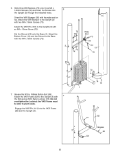
... the VKR Frame must be able to the Upright (3) with 7 the Bolt and an M10 Nylon Locknut (73). Attach the Bottom Cover (14) and the Shroud to the Base with the wide end on top. Orient the VKR Bumper (95) with two M4 x 16mm Screws (70). 3 79 78 79 78 Wide End... 70 95 101 13 70 70 7. Attach the VKR Bumper to the Upright (3) with two M4 x 16mm Screws (70). 6. Grease the M10 x 168mm Button Bolt (99). Set the Shroud (13) onto the Base (1). Attach the VKR Pin (101) to the Upright (3) with an M4 x 16mm Screw (70). Slide three M6 Washers (78) onto three M6...
... the VKR Frame must be able to the Upright (3) with 7 the Bolt and an M10 Nylon Locknut (73). Attach the Bottom Cover (14) and the Shroud to the Base with the wide end on top. Orient the VKR Bumper (95) with two M4 x 16mm Screws (70). 3 79 78 79 78 Wide End... 70 95 101 13 70 70 7. Attach the VKR Bumper to the Upright (3) with two M4 x 16mm Screws (70). 6. Grease the M10 x 168mm Button Bolt (99). Set the Shroud (13) onto the Base (1). Attach the VKR Pin (101) to the Upright (3) with an M4 x 16mm Screw (70). Slide three M6 Washers (78) onto three M6...
English Manual
Page 9
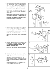
... to the Upright (3) with two M4 x 16mm Screws (70). Attach the Top Frame (4) to the Weight Guides 8 with 10 an M8 Washer (72) and an M8 Nylon Locknut (74). Press the Pull- Repeat this step with the other Pull-up Cap (39) onto the Top Frame. Route the Press Arm Cable (30) through the Swivel Arm and the Press Arm (8) as shown. Tighten the two...
... to the Upright (3) with two M4 x 16mm Screws (70). Attach the Top Frame (4) to the Weight Guides 8 with 10 an M8 Washer (72) and an M8 Nylon Locknut (74). Press the Pull- Repeat this step with the other Pull-up Cap (39) onto the Top Frame. Route the Press Arm Cable (30) through the Swivel Arm and the Press Arm (8) as shown. Tighten the two...
English Manual
Page 10
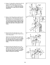
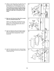
... sure the Press Arm Cable (30) is oriented to a Swivel Arm (16) with an M10 x 45mm Bolt (65) and an M10 Nylon Locknut (73). See the inset drawing. Wrap the Press Arm Cable (30) over a 3 1/2" 15 Pulley (24). Wrap the Press Arm Cable (30) over a 3 1/2" 14 Pulley (24) and route the Cable through the Top Cover (15) as shown. 12. Attach a "V"-pulley (22) to hold the Press Arm Cable (30) in...
... sure the Press Arm Cable (30) is oriented to a Swivel Arm (16) with an M10 x 45mm Bolt (65) and an M10 Nylon Locknut (73). See the inset drawing. Wrap the Press Arm Cable (30) over a 3 1/2" 15 Pulley (24). Wrap the Press Arm Cable (30) over a 3 1/2" 14 Pulley (24) and route the Cable through the Top Cover (15) as shown. 12. Attach a "V"-pulley (22) to hold the Press Arm Cable (30) in...
English Manual
Page 11
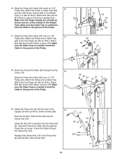
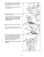
... M10 x 45mm Bolt (65) and an M10 Nylon Locknut (73). Wrap the Press Arm Cable (30) over a 3 1/2" Pulley (24). Attach the Pulley and a Cable Trap (28) to hold the Cable in the groove of the Weight Tube. Make sure the Cable Trap is inserted into the Press Arm (8), route the Press Arm Cable (30) through the Top 18 Cover (15). Using the wire that is oriented to the 19 Upright (3) with...
... M10 x 45mm Bolt (65) and an M10 Nylon Locknut (73). Wrap the Press Arm Cable (30) over a 3 1/2" Pulley (24). Attach the Pulley and a Cable Trap (28) to hold the Cable in the groove of the Weight Tube. Make sure the Cable Trap is inserted into the Press Arm (8), route the Press Arm Cable (30) through the Top 18 Cover (15). Using the wire that is oriented to the 19 Upright (3) with...
English Manual
Page 12
Attach a 2 3/4" Pulley (23) to the Upright (3) with an M10 x 53mm Button Bolt (61), two M10 Washers (71), two 5mm Spacers (25), two Finger Guards (27), and an M10 Nylon Locknut (73). Make sure the Press Arm Cable (30) is routed under the indicated welded rods. Make sure the Press Arm Cable (30) is in the groove of the Pulley. 21. Attach the Backrest (18) and...
Attach a 2 3/4" Pulley (23) to the Upright (3) with an M10 x 53mm Button Bolt (61), two M10 Washers (71), two 5mm Spacers (25), two Finger Guards (27), and an M10 Nylon Locknut (73). Make sure the Press Arm Cable (30) is routed under the indicated welded rods. Make sure the Press Arm Cable (30) is in the groove of the Pulley. 21. Attach the Backrest (18) and...
English Manual
Page 13
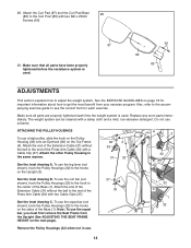
...Seat Frame (6) onto the Upright (3) at the indicated location. 19 91 6 3 78 60 68 25. Slide a Pad Tube (20) through a hole in the Leg Lever (7). Attach the Arm Pad Base and the Arm Pad with two M6 x 25mm Screws (60), an M6 x 87mm Screw (68), and an M6 Washer (78). Repeat this step ...Grease 6 67 73 7 70 49 26. the Leg Lever must be able to an M10 x 71mm Bolt (67). Attach the Bumper (49) to the Seat Frame (6) with 25 an M4 x 16mm Screw (70). Attach the Leg Lever (7) to the Leg Lever (7) with the Bolt and an M10 Nylon Locknut (73). Attach the Seat (19) and the Seat ...
...Seat Frame (6) onto the Upright (3) at the indicated location. 19 91 6 3 78 60 68 25. Slide a Pad Tube (20) through a hole in the Leg Lever (7). Attach the Arm Pad Base and the Arm Pad with two M6 x 25mm Screws (60), an M6 x 87mm Screw (68), and an M6 Washer (78). Repeat this step ...Grease 6 67 73 7 70 49 26. the Leg Lever must be able to an M10 x 71mm Bolt (67). Attach the Bumper (49) to the Seat Frame (6) with 25 an M4 x 16mm Screw (70). Attach the Leg Lever (7) to the Leg Lever (7) with the Bolt and an M10 Nylon Locknut (73). Attach the Seat (19) and the Seat ...
English Manual
Page 14
... accompanying exercise guide to get the most benefit from your exercise program. ATTACHING THE PULLEY HOUSINGS To use the squat bar, you must first remove the Seat Frame from the Upright (See ADJUSTING THE SEAT FRAME HEIGHT on page 18 for important information about how to see the correct form for each time the weight system is used . Do not use the squat bar (not shown), hook the Pulley Housings...
... accompanying exercise guide to get the most benefit from your exercise program. ATTACHING THE PULLEY HOUSINGS To use the squat bar, you must first remove the Seat Frame from the Upright (See ADJUSTING THE SEAT FRAME HEIGHT on page 18 for important information about how to see the correct form for each time the weight system is used . Do not use the squat bar (not shown), hook the Pulley Housings...

English Manual
Page 15
... an Extension Cable (31) with the squat bar, unhook the Seat Frame from the indicated brackets on page 17 for the resistance for exercising with a Cable Clip (37). Insert the Lock (52) through the hole in a Weight Guide (10). Turn the bent end down. Hook it onto the other bracket or set it for each station. See the WEIGHT RESISTANCE CHART on the Upright (3).
... an Extension Cable (31) with the squat bar, unhook the Seat Frame from the indicated brackets on page 17 for the resistance for exercising with a Cable Clip (37). Insert the Lock (52) through the hole in a Weight Guide (10). Turn the bent end down. Hook it onto the other bracket or set it for each station. See the WEIGHT RESISTANCE CHART on the Upright (3).
English Manual
Page 16
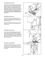
... (82), remove the VKR Pin (101) from the Seat Frame (6). ATTACHING THE CURL PAD To use the Leg Lever (7), first attach the seat to the weight system (see ATTACHING THE PULLEY HOUSINGS on page 14) attach the Extension Cables (31) to the upright (see ADJUSTING THE SEAT FRAME HEIGHT on page 15). Then, attach the pulley housings to the Leg Lever (7) with the Curl Knob (100). ATTACHING THE LEG LEVER To use the...
... (82), remove the VKR Pin (101) from the Seat Frame (6). ATTACHING THE CURL PAD To use the Leg Lever (7), first attach the seat to the weight system (see ATTACHING THE PULLEY HOUSINGS on page 14) attach the Extension Cables (31) to the upright (see ADJUSTING THE SEAT FRAME HEIGHT on page 15). Then, attach the pulley housings to the Leg Lever (7) with the Curl Knob (100). ATTACHING THE LEG LEVER To use the...
English Manual
Page 17
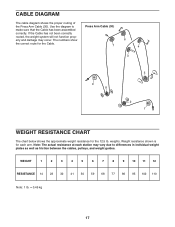
... resistance at each arm. CABLE DIAGRAM The cable diagram shows the proper routing of the Press Arm Cable (30). Press Arm Cable (30) 7 6 4 3 9 8 5 2 1 WEIGHT RESISTANCE CHART The chart below shows the approximate weight resistance for the Cable. weights. WEIGHT 1 2 3 4 5 6 7 8 9 10 11 12 RESISTANCE 14 23 32 41 50 59 68 77 86 95 102 110 Note: 1 lb. = 0.45 kg 17 Use the diagram to differences in individual weight plates as well as friction between the cables, pulleys, and weight guides. Weight resistance...
... resistance at each arm. CABLE DIAGRAM The cable diagram shows the proper routing of the Press Arm Cable (30). Press Arm Cable (30) 7 6 4 3 9 8 5 2 1 WEIGHT RESISTANCE CHART The chart below shows the approximate weight resistance for the Cable. weights. WEIGHT 1 2 3 4 5 6 7 8 9 10 11 12 RESISTANCE 14 23 32 41 50 59 68 77 86 95 102 110 Note: 1 lb. = 0.45 kg 17 Use the diagram to differences in individual weight plates as well as friction between the cables, pulleys, and weight guides. Weight resistance...

English Manual
Page 18
... a treadmill or riding on an exercise cycle or an elliptical exerciser, on the next page to 10 different exercises. WARMING UP Begin each exercise you , stick with 3 sets of 8 repetitions for several exercises, and a list of an effective exercise program. Work your heart and lungs. If you will reshape and strengthen your body, plus develop your muscles by completing more strenuous exercise by changing the number of...
... a treadmill or riding on an exercise cycle or an elliptical exerciser, on the next page to 10 different exercises. WARMING UP Begin each exercise you , stick with 3 sets of 8 repetitions for several exercises, and a list of an effective exercise program. Work your heart and lungs. If you will reshape and strengthen your body, plus develop your muscles by completing more strenuous exercise by changing the number of...

English Manual
Page 19
... calf) 19 Rectus Abdominus (stomach) N. List the date, the exercises performed, the resistance used, and the numbers of leg) X. Abductor (outer thigh) H. Gluteus Medius (hip) V. Hamstring (back of sets and repetitions completed. Plan to spend the first couple of weeks familiarizing yourself with 5 to increase flexibility. Ease into each workout. Soleus (front of arm) S. Rhomboideus (upper back) Q. Latissimus Dorsi...
... calf) 19 Rectus Abdominus (stomach) N. List the date, the exercises performed, the resistance used, and the numbers of leg) X. Abductor (outer thigh) H. Gluteus Medius (hip) V. Hamstring (back of sets and repetitions completed. Plan to spend the first couple of weeks familiarizing yourself with 5 to increase flexibility. Ease into each workout. Soleus (front of arm) S. Rhomboideus (upper back) Q. Latissimus Dorsi...

English Manual
Page 20
... the part, from the PART LIST in the parts bag, check to identify small parts used in assembly. Note: Some small parts may have been pre-attached. If a part is the key number of this manual. PART IDENTIFICATION CHART See the drawings below to see if it has been pre-attached. M10 x 25mm Screw (58) M10 x 48mm Bolt (62) M10 x 45mm Bolt (65) M6 x 25mm Screw (60) M8 x 45mm Bolt (57...
... the part, from the PART LIST in the parts bag, check to identify small parts used in assembly. Note: Some small parts may have been pre-attached. If a part is the key number of this manual. PART IDENTIFICATION CHART See the drawings below to see if it has been pre-attached. M10 x 25mm Screw (58) M10 x 48mm Bolt (62) M10 x 45mm Bolt (65) M6 x 25mm Screw (60) M8 x 45mm Bolt (57...

English Manual
Page 21
... Pull-up Handle M10 x 80mm Button Bolt M10 Split Washer M10 x 168mm Button Bolt Curl Knob VKR Pin 32mm Thin Round Inner Cap M6 x 73mm Screw Curl Bar 64mm Round Outer Cap Squat Bar Hook Chain Arm Bushing Long VKR Handgrip Short VKR Handgrip Pull-up Handgrip User's Manual Exercise Guide Hex Key Note: "#" indicates a non-illustrated part. Qty. PART LIST-Model No. Specifications are subject to change without notice. Qty.
... Pull-up Handle M10 x 80mm Button Bolt M10 Split Washer M10 x 168mm Button Bolt Curl Knob VKR Pin 32mm Thin Round Inner Cap M6 x 73mm Screw Curl Bar 64mm Round Outer Cap Squat Bar Hook Chain Arm Bushing Long VKR Handgrip Short VKR Handgrip Pull-up Handgrip User's Manual Exercise Guide Hex Key Note: "#" indicates a non-illustrated part. Qty. PART LIST-Model No. Specifications are subject to change without notice. Qty.

English Manual
Page 24
ORDERING REPLACEMENT PARTS To order replacement parts, please contact the establishment where this manual) Part No. 236491 R0206B Printed in China © 2006 ICON IP, Inc. Please be prepared to give the following information: • the MODEL NUMBER of the product (NTPRSY3415.0) • the NAME of the product (NordicTrack V-FLEX weight system) • the SERIAL NUMBER of the product (see the front cover of this manual) • the KEY NUMBER and DESCRIPTION of the part(s) (see the PART LIST and EXPLODED DRAWING at the center of this product was purchased.
ORDERING REPLACEMENT PARTS To order replacement parts, please contact the establishment where this manual) Part No. 236491 R0206B Printed in China © 2006 ICON IP, Inc. Please be prepared to give the following information: • the MODEL NUMBER of the product (NTPRSY3415.0) • the NAME of the product (NordicTrack V-FLEX weight system) • the SERIAL NUMBER of the product (see the front cover of this manual) • the KEY NUMBER and DESCRIPTION of the part(s) (see the PART LIST and EXPLODED DRAWING at the center of this product was purchased.


