
Uk Manual
Page 2
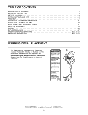
... the location shown. User weight must not exceed 275 pounds. NORDICTRACK is missing or illegible, see the front cover of ICON IP, Inc. 2 TABLE OF CONTENTS WARNING DECAL PLACEMENT 2 IMPORTANT PRECAUTIONS 3 BEFORE YOU BEGIN 4 PART IDENTIFICATION CHART 5 ASSEMBLY 6 HOW TO USE THE HEART RATE MONITOR 11 HOW TO USE THE EXERCISE BIKE 12 MAINTENANCE AND TROUBLESHOOTING 21 EXERCISE GUIDELINES 23 PART LIST 25 EXPLODED DRAWING 27 ORDERING REPLACEMENT PARTS Back Cover RECYCLING INFORMATION Back Cover WARNING...
... the location shown. User weight must not exceed 275 pounds. NORDICTRACK is missing or illegible, see the front cover of ICON IP, Inc. 2 TABLE OF CONTENTS WARNING DECAL PLACEMENT 2 IMPORTANT PRECAUTIONS 3 BEFORE YOU BEGIN 4 PART IDENTIFICATION CHART 5 ASSEMBLY 6 HOW TO USE THE HEART RATE MONITOR 11 HOW TO USE THE EXERCISE BIKE 12 MAINTENANCE AND TROUBLESHOOTING 21 EXERCISE GUIDELINES 23 PART LIST 25 EXPLODED DRAWING 27 ORDERING REPLACEMENT PARTS Back Cover RECYCLING INFORMATION Back Cover WARNING...
Uk Manual
Page 3
... times. 9. The exercise bike is especially important for home use only. The pulse sensor is the responsibility of the owner to ensure that could become caught on the exercise bike. Over exercising may affect the accuracy of heart rate readings. Before beginning any worn parts immediately. 3 do not arch your physician. It is intended only as described in this manual. 8. Keep the exercise bike indoors, away...
... times. 9. The exercise bike is especially important for home use only. The pulse sensor is the responsibility of the owner to ensure that could become caught on the exercise bike. Over exercising may affect the accuracy of heart rate readings. Before beginning any worn parts immediately. 3 do not arch your physician. It is intended only as described in this manual. 8. Keep the exercise bike indoors, away...
Uk Manual
Page 4
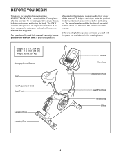
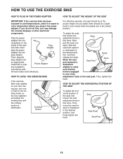
... manual, please see the front cover of the serial number decal are labeled in . (58 cm) Weight: 82 lbs. (37 kg) Handgrip Pulse Sensor Seat Seat Adjustment Knob Seat Post Leveling Knob Leveling Foot Console Handlebar Adjustment Knob Seat Post Knob Pedal/Strap Wheel 4 Cycling is an effective exercise for selecting the revolutionary NORDICTRACK® GX 4.1 exercise bike. For your workouts at home more effective and enjoyable. To help us assist you, note the product model number and serial number...
... manual, please see the front cover of the serial number decal are labeled in . (58 cm) Weight: 82 lbs. (37 kg) Handgrip Pulse Sensor Seat Seat Adjustment Knob Seat Post Leveling Knob Leveling Foot Console Handlebar Adjustment Knob Seat Post Knob Pedal/Strap Wheel 4 Cycling is an effective exercise for selecting the revolutionary NORDICTRACK® GX 4.1 exercise bike. For your workouts at home more effective and enjoyable. To help us assist you, note the product model number and serial number...

Uk Manual
Page 8
5. Attach the Console (13) to the Upright (4) with four M4 x 16mm Screws (90). Then, attach an M6 x 60mm Bolt Set (51) through the Handlebar as shown. While another person holds the Console (13) near the Upright (4), insert the Extension Wire (59) upward through the Handlebar. Avoid pinching the wires 13 61 5 59 A 90 8 Tip: Avoid pinching the Extension Wire (59). Then, connect the other...
5. Attach the Console (13) to the Upright (4) with four M4 x 16mm Screws (90). Then, attach an M6 x 60mm Bolt Set (51) through the Handlebar as shown. While another person holds the Console (13) near the Upright (4), insert the Extension Wire (59) upward through the Handlebar. Avoid pinching the wires 13 61 5 59 A 90 8 Tip: Avoid pinching the Extension Wire (59). Then, connect the other...

Uk Manual
Page 9
... wires. Orient the Upright (4) assembly and the Pivot Cover (12) as shown. Attach the Upright (4) with two M4 x 16mm Screws (90) and two M4 x 22mm Screws (94). Tip: Bend and flex the Pivot Cover slightly to the Frame (1) and press it over the Handlebar. Attach the Pivot Cover (12) to the Handlebar (5). Avoid pinching the wires 4 7 59 75 1 58 74 75 74 75 9 7. Tighten an Adjustment Knob...
... wires. Orient the Upright (4) assembly and the Pivot Cover (12) as shown. Attach the Upright (4) with two M4 x 16mm Screws (90) and two M4 x 22mm Screws (94). Tip: Bend and flex the Pivot Cover slightly to the Frame (1) and press it over the Handlebar. Attach the Pivot Cover (12) to the Handlebar (5). Avoid pinching the wires 4 7 59 75 1 58 74 75 74 75 9 7. Tighten an Adjustment Knob...
Uk Manual
Page 10
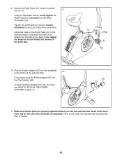
...). Adjust the strap on the Right Pedal (21) to protect the floor or carpet. 10 Plug the Power Adapter (67) into the Plug Adapter (98). Tighten the Left Pedal (not shown) counterclockwise into the Right Crank Arm (19). Adjust the strap on the frame of the straps onto the tabs on page 12. 98 67 11. 9. Make sure that all parts are properly tightened before you use the exercise bike...
...). Adjust the strap on the Right Pedal (21) to protect the floor or carpet. 10 Plug the Power Adapter (67) into the Plug Adapter (98). Tighten the Left Pedal (not shown) counterclockwise into the Right Crank Arm (19). Adjust the strap on the frame of the straps onto the tabs on page 12. 98 67 11. 9. Make sure that all parts are properly tightened before you use the exercise bike...
Uk Manual
Page 11
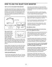
... using or storing the heart rate monitor. sor unit. Pull the sensor unit away from your body a few inches and locate the two electrode areas on the sensor unit is facing forward and is activated when you wet the electrode areas and put on the chest strap. The heart rate monitor is right- the heart TROUBLESHOOTING If the heart rate monitor does not function properly, try relocating the exercise bike...
... using or storing the heart rate monitor. sor unit. Pull the sensor unit away from your body a few inches and locate the two electrode areas on the sensor unit is facing forward and is activated when you wet the electrode areas and put on the chest strap. The heart rate monitor is right- the heart TROUBLESHOOTING If the heart rate monitor does not function properly, try relocating the exercise bike...
Uk Manual
Page 12
... the adjustment holes in accordance with all local codes and ordinances. ward, slide the seat post upward or downward to the desired position, and firmly tighten the knob. Then, move the seat forward or backward to the desired position, and then Holes release the knob. Plug the power adapter into the plug adapter. Power Adapter erly installed in the seat post. HOW TO LEVEL THE EXERCISE BIKE If the exercise bike...
... the adjustment holes in accordance with all local codes and ordinances. ward, slide the seat post upward or downward to the desired position, and firmly tighten the knob. Then, move the seat forward or backward to the desired position, and then Holes release the knob. Plug the power adapter into the plug adapter. Power Adapter erly installed in the seat post. HOW TO LEVEL THE EXERCISE BIKE If the exercise bike...
Uk Manual
Page 14
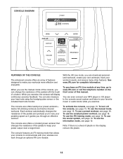
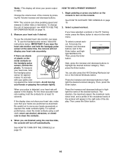
... information. The console also offers twenty-four preset workouts- To use the iFit training mode, see page 15. Note: If there is a sheet of plastic on the front cover of a button. The console features an iFit training mode that changes the resistance of the pedals with your heart rate using the handgrip pulse sensor or the included heart rate monitor. To use the manual mode, see page 19. To turn off the console, see page 15. To use the constant power workout...
... information. The console also offers twenty-four preset workouts- To use the iFit training mode, see page 15. Note: If there is a sheet of plastic on the front cover of a button. The console features an iFit training mode that changes the resistance of the pedals with your heart rate using the handgrip pulse sensor or the included heart rate monitor. To use the manual mode, see page 19. To turn off the console, see page 15. To use the constant power workout...
Uk Manual
Page 15
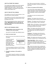
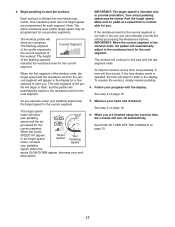
... finished exercising, unplug the power adapter. Distance-This display mode will show the resistance level of the pedals as desired. HOW TO TURN OFF THE CONSOLE If the pedals do this display mode will be reset. Resistance-This display mode will be used to reach the selected resistance level. 4. Follow your pedaling speed in miles or kilometers. If you have selected a workout or the iFit Training mode, press the Menu button to return to the Enter button and highlight START...
... finished exercising, unplug the power adapter. Distance-This display mode will show the resistance level of the pedals as desired. HOW TO TURN OFF THE CONSOLE If the pedals do this display mode will be reset. Resistance-This display mode will be used to reach the selected resistance level. 4. Follow your pedaling speed in miles or kilometers. If you have selected a workout or the iFit Training mode, press the Menu button to return to the Enter button and highlight START...
Uk Manual
Page 16
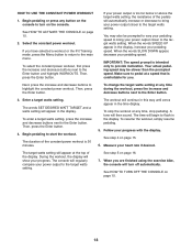
... a workout or the iFit Training mode, press the Menu button to return to turn off automatically. Contacts mately 15 seconds with your hands or gripping the contacts tightly. If you wear the heart rate monitor and hold the handgrip pulse sensor for at the same time, the console will not display your power output in watts. Be careful not to clean the contacts. To use the...
... a workout or the iFit Training mode, press the Menu button to return to turn off automatically. Contacts mately 15 seconds with your hands or gripping the contacts tightly. If you wear the heart rate monitor and hold the handgrip pulse sensor for at the same time, the console will not display your power output in watts. Be careful not to clean the contacts. To use the...
Uk Manual
Page 17
... the next segment. See HOW TO TURN OFF THE CONSOLE on page 15. The height of the profile will turn off automatically. Your actual pedaling speed may be slower than the target speed. To resume the workout, simply resume pedaling. 4. See step 4 on page 15. 17 When you can manually override the setting by pressing the Resistance buttons. One resistance level and one -minute segments...
... the next segment. See HOW TO TURN OFF THE CONSOLE on page 15. The height of the profile will turn off automatically. Your actual pedaling speed may be slower than the target speed. To resume the workout, simply resume pedaling. 4. See step 4 on page 15. 17 When you can manually override the setting by pressing the Resistance buttons. One resistance level and one -minute segments...
Uk Manual
Page 18
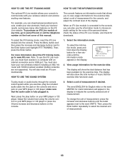
... turn on page 15. 2. During the workout, the display will regularly compare your power output closer to turn off automatically. See step 5 on page 16. 7. Then, press the Enter button. When you have selected a workout or the iFit Training mode, press the Menu button to return to pedal at the top of the pedals will then sound. If you are finished using the exercise bike, the console will appear at a speed...
... turn on page 15. 2. During the workout, the display will regularly compare your power output closer to turn off automatically. See step 5 on page 16. 7. Then, press the Enter button. When you have selected a workout or the iFit Training mode, press the Menu button to return to pedal at the top of the pedals will then sound. If you are finished using the exercise bike, the console will appear at a speed...
Uk Manual
Page 19
... will also need an iFit.com membership. To change the unit of measurement if desired. The display will also show the total distance that allows you exercise, plug the included audio cable into the jack on the console and into the console. Press the Menu button and then press the increase and decrease buttons next to www.iFit.com or call the telephone number on the exercise bike. You...
... will also need an iFit.com membership. To change the unit of measurement if desired. The display will also show the total distance that allows you exercise, plug the included audio cable into the jack on the console and into the console. Press the Menu button and then press the increase and decrease buttons next to www.iFit.com or call the telephone number on the exercise bike. You...
Uk Manual
Page 21
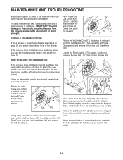
.... If the console does not display your heart rate when you must first remove the left pedal, the left disc cover, and the left Pedal Disc upward and remove it from the Left Crank Arm (20). MAINTENANCE AND TROUBLESHOOTING Inspect and tighten all parts of direct sunlight. Rotate the left pedal. 21 Slide the Reed Switch slightly toward or away from the console and keep the console out of the exercise bike regularly...
.... If the console does not display your heart rate when you must first remove the left pedal, the left disc cover, and the left Pedal Disc upward and remove it from the Left Crank Arm (20). MAINTENANCE AND TROUBLESHOOTING Inspect and tighten all parts of direct sunlight. Rotate the left pedal. 21 Slide the Reed Switch slightly toward or away from the console and keep the console out of the exercise bike regularly...
Uk Manual
Page 22
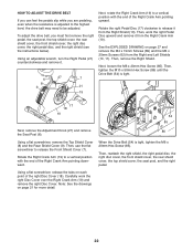
..., work the right Disc Cover over the Right Crank Arm (19) and remove the right Disc Cover. Then, reattach the right shield, the right pedal disc, the right disc cover, the front shield cover, the rear shield cover, the top shield cover, the seat post, and the right pedal. 22 To adjust the drive belt, you are pedaling, even when the resistance is adjusted to the highest level, the drive belt may need...
..., work the right Disc Cover over the Right Crank Arm (19) and remove the right Disc Cover. Then, reattach the right shield, the right pedal disc, the right disc cover, the front shield cover, the rear shield cover, the top shield cover, the seat post, and the right pedal. 22 To adjust the drive belt, you are pedaling, even when the resistance is adjusted to the highest level, the drive belt may need...

Uk Manual
Page 23
... condition, complete three workouts each week, if desired. Remember, the key to success is the key to plan your heart rate as an exercise aid in determining heart rate trends in your breath. The pulse sensor is intended only as a guide to find your training zone for 20 to make exercise a regular and enjoyable part of your exercise program, do not keep your heart rate in your age...
... condition, complete three workouts each week, if desired. Remember, the key to success is the key to plan your heart rate as an exercise aid in determining heart rate trends in your breath. The pulse sensor is intended only as a guide to find your training zone for 20 to make exercise a regular and enjoyable part of your exercise program, do not keep your heart rate in your age...
Uk Manual
Page 25
... 1 83 1 84 1 85 1 86 1 87 1 88 1 89 14 90 8 Description Motor Bracket Resistance Motor Resistance Disc Resistance Arm M6 x 70mm Bolt Set M6 x 60mm Bolt Set Resistance Bracket C-magnet Drive Belt Magnet Clamp Reed Switch/Wire Main Wire Extension Wire Wire Clamp Pulse Wire M4 x 25mm Screw M4 x 12.7mm Flange Screw Audio Cable M8 x 17mm Flat Head Screw Handlebar Cap Power Adapter Crank Cap Upright Pivot Bushing 5/16" Flange Screw M8 x 20mm Button Bolt M8 Locknut M8 Jam Nut M8 x 20mm Patch...
... 1 83 1 84 1 85 1 86 1 87 1 88 1 89 14 90 8 Description Motor Bracket Resistance Motor Resistance Disc Resistance Arm M6 x 70mm Bolt Set M6 x 60mm Bolt Set Resistance Bracket C-magnet Drive Belt Magnet Clamp Reed Switch/Wire Main Wire Extension Wire Wire Clamp Pulse Wire M4 x 25mm Screw M4 x 12.7mm Flange Screw Audio Cable M8 x 17mm Flat Head Screw Handlebar Cap Power Adapter Crank Cap Upright Pivot Bushing 5/16" Flange Screw M8 x 20mm Button Bolt M8 Locknut M8 Jam Nut M8 x 20mm Patch...

Uk Manual
Page 26
Qty. Description 91 2 M4 x 5mm Patch Screw 92 2 Handlebar Pivot Bushing 93 6 M4 x 19mm Flat Head Screw 94 2 M4 x 22mm Screw 95 1 Power Receptacle/Wire 96 1 Snap Ring 97 2 Adjustment Nut 98 1 99 1 100 1 * - * - * - Plug Adapter Sensor Strap Receiver Wire Assembly Tool Userʼs Manual Note: Specifications are not illustrated. 26 For information about ordering replacement parts, see the back cover of this manual. *These parts are subject to change without notice. Key No. Description Key No. Qty.
Qty. Description 91 2 M4 x 5mm Patch Screw 92 2 Handlebar Pivot Bushing 93 6 M4 x 19mm Flat Head Screw 94 2 M4 x 22mm Screw 95 1 Power Receptacle/Wire 96 1 Snap Ring 97 2 Adjustment Nut 98 1 99 1 100 1 * - * - * - Plug Adapter Sensor Strap Receiver Wire Assembly Tool Userʼs Manual Note: Specifications are not illustrated. 26 For information about ordering replacement parts, see the back cover of this manual. *These parts are subject to change without notice. Key No. Description Key No. Qty.
Uk Manual
Page 28
... to provide the following information when contacting us: • the model number and serial number of the product (see the front cover of this manual) • the name of the product (see the front cover of this manual) • the key number and description of the replacement part(s) (see the front cover of this manual. ORDERING REPLACEMENT PARTS To order replacement parts, please see the PART LIST and the EXPLODED DRAWING...
... to provide the following information when contacting us: • the model number and serial number of the product (see the front cover of this manual) • the name of the product (see the front cover of this manual) • the key number and description of the replacement part(s) (see the front cover of this manual. ORDERING REPLACEMENT PARTS To order replacement parts, please see the PART LIST and the EXPLODED DRAWING...


