
English Manual
Page 2
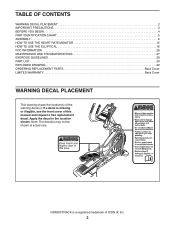
...NORDICTRACK is missing or illegible, see the front cover of this manual and request a free replacement decal. Note: The decal(s) may not be shown at actual size. Apply the decal in the location shown. TABLE OF CONTENTS WARNING DECAL PLACEMENT 2 IMPORTANT PRECAUTIONS 3 BEFORE YOU BEGIN 4 PART IDENTIFICATION CHART 5 ASSEMBLY... 6 HOW TO USE THE HEART RATE MONITOR 15 HOW TO USE THE ELLIPTICAL 16 FCC INFORMATION 26 MAINTENANCE AND TROUBLESHOOTING 27 EXERCISE GUIDELINES 29 PART LIST 30...
...NORDICTRACK is missing or illegible, see the front cover of this manual and request a free replacement decal. Note: The decal(s) may not be shown at actual size. Apply the decal in the location shown. TABLE OF CONTENTS WARNING DECAL PLACEMENT 2 IMPORTANT PRECAUTIONS 3 BEFORE YOU BEGIN 4 PART IDENTIFICATION CHART 5 ASSEMBLY... 6 HOW TO USE THE HEART RATE MONITOR 15 HOW TO USE THE ELLIPTICAL 16 FCC INFORMATION 26 MAINTENANCE AND TROUBLESHOOTING 27 EXERCISE GUIDELINES 29 PART LIST 30...
English Manual
Page 5
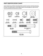
... see if it has been preassembled. The number in the hardware kit, check to identify the small parts needed for assembly. The number following the key number is the quantity needed for assembly. M8 Locknut (102)-4 M8 Star Washer (122)-4 Wave Washer (95)-2 M8 x 25mm Washer (98)-6 #8 x 1/2" Screw (124)-4 #8 x 3/4" Screw (123)-11...
... see if it has been preassembled. The number in the hardware kit, check to identify the small parts needed for assembly. The number following the key number is the quantity needed for assembly. M8 Locknut (102)-4 M8 Star Washer (122)-4 Wave Washer (95)-2 M8 x 25mm Washer (98)-6 #8 x 1/2" Screw (124)-4 #8 x 3/4" Screw (123)-11...
English Manual
Page 6
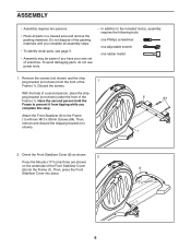
... shown) from tipping while you have your own set of the 1 Frame (1). Attach the Front Stabilizer (6) to the included tool(s), assembly requires the following tools: one Phillips screwdriver one adjustable wrench one rubber mallet 1. With the help of a second person, place the ... of the Frame (1). Then, remove and discard the shipping bracket (not shown). 6 84 1 2. ASSEMBLY • Assembly requires two persons. • Place all assembly steps. • To identify small parts, see page 5. • Assembly may be easier if you complete this step. Discard the screws.
... shown) from tipping while you have your own set of the 1 Frame (1). Attach the Front Stabilizer (6) to the included tool(s), assembly requires the following tools: one Phillips screwdriver one adjustable wrench one rubber mallet 1. With the help of a second person, place the ... of the Frame (1). Then, remove and discard the shipping bracket (not shown). 6 84 1 2. ASSEMBLY • Assembly requires two persons. • Place all assembly steps. • To identify small parts, see page 5. • Assembly may be easier if you complete this step. Discard the screws.
English Manual
Page 14
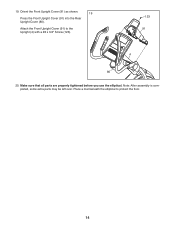
Attach the Front Upright Cover (91) to protect the floor. 14 Place a mat beneath the elliptical to the Upright (4) with a #8 x 3/4" Screw (123). 123 91 4 80 20. Orient the Front Upright Cover (91) as shown. 19 Press the Front Upright Cover (91) into the Rear Upright Cover (80). pleted, some extra parts may be left over. Note: After assembly is com- 19. Make sure that all parts are properly tightened before you use the elliptical.
Attach the Front Upright Cover (91) to protect the floor. 14 Place a mat beneath the elliptical to the Upright (4) with a #8 x 3/4" Screw (123). 123 91 4 80 20. Orient the Front Upright Cover (91) as shown. 19 Press the Front Upright Cover (91) into the Rear Upright Cover (80). pleted, some extra parts may be left over. Note: After assembly is com- 19. Make sure that all parts are properly tightened before you use the elliptical.
English Manual
Page 31
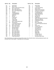
... Pedal Adjustment Bracket Adjustment Bushing Pedal Bracket Screw Knob Pin M10 x 56mm Bolt Left Pedal Adjustment Bracket Foot Nylon Insert Lift Motor Bushing User's Manual Assembly Tool Grease Packet Blue Wire Green Wire White Wire Lift Motor Wire A Lift Motor Wire B Resistance Motor Wire Note: Specifications are not illustrated. 31 Qty...
... Pedal Adjustment Bracket Adjustment Bushing Pedal Bracket Screw Knob Pin M10 x 56mm Bolt Left Pedal Adjustment Bracket Foot Nylon Insert Lift Motor Bushing User's Manual Assembly Tool Grease Packet Blue Wire Green Wire White Wire Lift Motor Wire A Lift Motor Wire B Resistance Motor Wire Note: Specifications are not illustrated. 31 Qty...


