

English Manual
Page 2
TABLE OF CONTENTS WARNING DECAL PLACEMENT 2 IMPORTANT PRECAUTIONS 3 BEFORE YOU BEGIN 7 PART IDENTIFICATION CHART 8 ASSEMBLY 9 HOW TO USE THE ELLIPTICAL 18 FCC INFORMATION 35 MAINTENANCE AND TROUBLESHOOTING 36 EXERCISE GUIDELINES 38 PART LIST 39 EXPLODED DRAWING 41 ORDERING REPLACEMENT... shown at actual size. IFIT is a registered trademark of the warning decal(s). WPA and WPA2 are trademarks of ICON Health & Fitness, Inc. NORDICTRACK is a trademark of this manual and request a free replacement decal. Google Maps is a registered trademark of Wi-Fi Alliance. 2 Apply the ...
TABLE OF CONTENTS WARNING DECAL PLACEMENT 2 IMPORTANT PRECAUTIONS 3 BEFORE YOU BEGIN 7 PART IDENTIFICATION CHART 8 ASSEMBLY 9 HOW TO USE THE ELLIPTICAL 18 FCC INFORMATION 35 MAINTENANCE AND TROUBLESHOOTING 36 EXERCISE GUIDELINES 38 PART LIST 39 EXPLODED DRAWING 41 ORDERING REPLACEMENT... shown at actual size. IFIT is a registered trademark of the warning decal(s). WPA and WPA2 are trademarks of ICON Health & Fitness, Inc. NORDICTRACK is a trademark of this manual and request a free replacement decal. Google Maps is a registered trademark of Wi-Fi Alliance. 2 Apply the ...

English Manual
Page 8
... x 38mm Bolt (96)-4 M10 x 25mm Screw (99)-4 M10 x 122mm Screw (104)-4 8 PART IDENTIFICATION CHART Use the drawings below each drawing is the quantity needed for assembly. The number following the key number is the key number of the part, from the PART LIST near the end of this manual. The number...
... x 38mm Bolt (96)-4 M10 x 25mm Screw (99)-4 M10 x 122mm Screw (104)-4 8 PART IDENTIFICATION CHART Use the drawings below each drawing is the quantity needed for assembly. The number following the key number is the key number of the part, from the PART LIST near the end of this manual. The number...
English Manual
Page 9
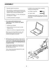
... need to contact Customer Care • allows us to the included tool(s), assembly requires the following tools: one Phillips screwdriver one rubber mallet Assembly may be easier if you do not use power tools. 1. ASSEMBLY • Assembly requires two persons. • Place all assembly steps. • Left parts are marked "L" or "Left" and right parts...
... need to contact Customer Care • allows us to the included tool(s), assembly requires the following tools: one Phillips screwdriver one rubber mallet Assembly may be easier if you do not use power tools. 1. ASSEMBLY • Assembly requires two persons. • Place all assembly steps. • Left parts are marked "L" or "Left" and right parts...
English Manual
Page 37
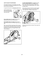
... (89). To adjust the drive belt, first unplug the power cord. Then, retighten the Idler Screw. 113 See assembly step 15 on page 43. Remove the Right Pedal Arm (58) from the elliptical. 89 91 Reattach the parts that you are pedaling, even while the resistance is tight. Then, carefully remove the... Right Shields. Using a standard screwdriver, remove the Shield Cover (75) and the Shield Cover Cap (118). 118 75 See EXPLODED DRAWING C on page 16. See assembly step 12 on page 14. Then, remove the Right Shield.
... (89). To adjust the drive belt, first unplug the power cord. Then, retighten the Idler Screw. 113 See assembly step 15 on page 43. Remove the Right Pedal Arm (58) from the elliptical. 89 91 Reattach the parts that you are pedaling, even while the resistance is tight. Then, carefully remove the... Right Shields. Using a standard screwdriver, remove the Shield Cover (75) and the Shield Cover Cap (118). 118 75 See EXPLODED DRAWING C on page 16. See assembly step 12 on page 14. Then, remove the Right Shield.

English Manual
Page 39
... Washer Small Axle Cover Roller Arm Bushing Arm Bearing Right Pedal Arm Right Roller Arm Right Upper Body Leg Right Upper Body Arm Grip Sensor Assembly/Wire Pedal Arm Axle Right Arm Front Cover Right Arm Rear Cover Left Arm Front Cover Left Arm Rear Cover Right Leg Outer Cover Left...
... Washer Small Axle Cover Roller Arm Bushing Arm Bearing Right Pedal Arm Right Roller Arm Right Upper Body Leg Right Upper Body Arm Grip Sensor Assembly/Wire Pedal Arm Axle Right Arm Front Cover Right Arm Rear Cover Left Arm Front Cover Left Arm Rear Cover Right Leg Outer Cover Left...

English Manual
Page 40
... M6 Small Washer M6 x 12mm Screw Left Front Handlebar Cover Left Rear Handlebar Cover Right Front Handlebar Cover Right Rear Handlebar Cover M4 x 25mm Screw Assembly Tool Grease Packet User's Manual Note: Specifications are not illustrated. 40 Qty. Key No. Description 101 35 102 6 103 8 104 4 105 8 106 3 107 1 108 2 109...
... M6 Small Washer M6 x 12mm Screw Left Front Handlebar Cover Left Rear Handlebar Cover Right Front Handlebar Cover Right Rear Handlebar Cover M4 x 25mm Screw Assembly Tool Grease Packet User's Manual Note: Specifications are not illustrated. 40 Qty. Key No. Description 101 35 102 6 103 8 104 4 105 8 106 3 107 1 108 2 109...


