

English Manual
Page 2
... decal in the location shown. NORDICTRACK is a trademark of the warning decal(s). Wi-Fi is a registered trademark of Wi-Fi Alliance. 2 TABLE OF CONTENTS WARNING DECAL PLACEMENT 2 IMPORTANT PRECAUTIONS 3 BEFORE YOU BEGIN 7 PART IDENTIFICATION CHART 8 ASSEMBLY 9 HOW TO USE THE ELLIPTICAL 18 FCC INFORMATION 35 MAINTENANCE AND TROUBLESHOOTING 36 EXERCISE GUIDELINES 38 PART LIST 39 EXPLODED DRAWING 41 ORDERING REPLACEMENT PARTS Back Cover LIMITED WARRANTY Back Cover WARNING DECAL...
... decal in the location shown. NORDICTRACK is a trademark of the warning decal(s). Wi-Fi is a registered trademark of Wi-Fi Alliance. 2 TABLE OF CONTENTS WARNING DECAL PLACEMENT 2 IMPORTANT PRECAUTIONS 3 BEFORE YOU BEGIN 7 PART IDENTIFICATION CHART 8 ASSEMBLY 9 HOW TO USE THE ELLIPTICAL 18 FCC INFORMATION 35 MAINTENANCE AND TROUBLESHOOTING 36 EXERCISE GUIDELINES 38 PART LIST 39 EXPLODED DRAWING 41 ORDERING REPLACEMENT PARTS Back Cover LIMITED WARRANTY Back Cover WARNING DECAL...
English Manual
Page 3
... in this manual should not be performed by persons weighing more than 350 lbs. (159 kg). 15. Inspect and properly tighten all parts each side. Replace any exercise program, consult your elliptical. ICON assumes no responsibility for use by or through the use an adapter to connect the power cord to ensure that could become caught on the elliptical. Do not modify the power cord or use of...
... in this manual should not be performed by persons weighing more than 350 lbs. (159 kg). 15. Inspect and properly tighten all parts each side. Replace any exercise program, consult your elliptical. ICON assumes no responsibility for use by or through the use an adapter to connect the power cord to ensure that could become caught on the elliptical. Do not modify the power cord or use of...

English Manual
Page 7
... you have questions after reading this manual. The model number and the location of this manual, please see the front cover of the serial number decal are labeled in . (86 cm) Upper Body Arm Handlebar Fan Accessory Tray Tablet Holder Console Heart Rate Monitor Speaker Pedal Pedal Handle Roller Handle Leveling Foot Power Switch Power Cord Wheel Ramp 7 Before reading further, please familiarize yourself with the parts that are shown on the...
... you have questions after reading this manual. The model number and the location of this manual, please see the front cover of the serial number decal are labeled in . (86 cm) Upper Body Arm Handlebar Fan Accessory Tray Tablet Holder Console Heart Rate Monitor Speaker Pedal Pedal Handle Roller Handle Leveling Foot Power Switch Power Cord Wheel Ramp 7 Before reading further, please familiarize yourself with the parts that are shown on the...
English Manual
Page 14
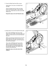
... the Right Upper Body Leg (60), insert the Pedal Arm Axle (64) into the Pedal Arm Axle (64). Repeat this step for the Left Pedal Arm (44). 44 79 55 97 59 Grease 58 12. Attach the Right Pedal Arm (58) to the Right Roller Arm (59) with an M8 x 14mm Shoulder Screw (79), a Small Axle Cover (55), and an M8 Washer (97). Then, tighten both parts. While a second...
... the Right Upper Body Leg (60), insert the Pedal Arm Axle (64) into the Pedal Arm Axle (64). Repeat this step for the Left Pedal Arm (44). 44 79 55 97 59 Grease 58 12. Attach the Right Pedal Arm (58) to the Right Roller Arm (59) with an M8 x 14mm Shoulder Screw (79), a Small Axle Cover (55), and an M8 Washer (97). Then, tighten both parts. While a second...

English Manual
Page 18
... the risk of electric shock. Do not modify the plug-if it should be used to connect the power cord to determine whether the outlet box cover is not available. 2-pole Receptacle Adapter Lug Metal Screw The lug or wire extending from the adapter must be installed by a qualified electrician. Before using an adapter, contact a qualified electrician to a 2-pole receptacle as...
... the risk of electric shock. Do not modify the plug-if it should be used to connect the power cord to determine whether the outlet box cover is not available. 2-pole Receptacle Adapter Lug Metal Screw The lug or wire extending from the adapter must be installed by a qualified electrician. Before using an adapter, contact a qualified electrician to a 2-pole receptacle as...

English Manual
Page 22
... console displays or other features. Each workout automatically controls the resistance of the pedals and the incline of the ramp and prompts you to vary your heart rate using the handgrip heart rate monitor. To set -a-goal workout. Press the power switch to the reset position. Reset Position The display will then turn on the power, see step 6 on , the console will be used if the elliptical is displayed in the power cord (see page 23. When the ramp stops moving, the incline...
... console displays or other features. Each workout automatically controls the resistance of the pedals and the incline of the ramp and prompts you to vary your heart rate using the handgrip heart rate monitor. To set -a-goal workout. Press the power switch to the reset position. Reset Position The display will then turn on the power, see step 6 on , the console will be used if the elliptical is displayed in the power cord (see page 23. When the ramp stops moving, the incline...
English Manual
Page 23
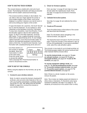
... ready for firmware updates. Connect to your finger against the screen to move certain images on the console to access the Internet, download iFit workouts, and use the wireless network mode, see step 14 on page 32 and check for your fingers on the screen, remove the plastic. Touch the globe button at the bottom of plastic on the screen. • To type information into...
... ready for firmware updates. Connect to your finger against the screen to move certain images on the console to access the Internet, download iFit workouts, and use the wireless network mode, see step 14 on page 32 and check for your fingers on the screen, remove the plastic. Touch the globe button at the bottom of plastic on the screen. • To type information into...
English Manual
Page 26
... workout is displayed in revolutions per minute (rpm). Begin pedaling or press any button on the console to start the workout. See step 2 on the screen to select the desired map options. Touch the Start Workout button to turn on the screen. To view the target zone meter, flick or slide the screen. Your actual pedaling speed may be slower than the target cadence. HOW TO USE...
... workout is displayed in revolutions per minute (rpm). Begin pedaling or press any button on the console to start the workout. See step 2 on the screen to select the desired map options. Touch the Start Workout button to turn on the screen. To view the target zone meter, flick or slide the screen. Your actual pedaling speed may be slower than the target cadence. HOW TO USE...
English Manual
Page 27
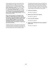
... Workout button. Follow your heart rate if desired. Turn on page 24). When you burn will appear on page 25. 27 If you press a Resistance button, you can manually override the setting by pressing the Resistance buttons or the Ramp buttons. The actual number of calories you are finished exercising, unplug the power cord. You may also be affected. Measure your progress. In addition, if you manually change the resistance or incline...
... Workout button. Follow your heart rate if desired. Turn on page 24). When you burn will appear on page 25. 27 If you press a Resistance button, you can manually override the setting by pressing the Resistance buttons or the Ramp buttons. The actual number of calories you are finished exercising, unplug the power cord. You may also be affected. Measure your progress. In addition, if you manually change the resistance or incline...
English Manual
Page 28
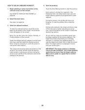
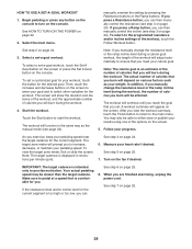
... you can then manually control the incline (see step 3 on the console. Begin pedaling or press any button on the screen to pedal at a speed that is intended only to the programmed resistance and/or incline settings of the workout will be able to increase, decrease, or maintain your workout, touch the button for your pedaling speed. Select the main menu. Make sure to enter your weight. To return to...
... you can then manually control the incline (see step 3 on the console. Begin pedaling or press any button on the screen to pedal at a speed that is intended only to the programmed resistance and/or incline settings of the workout will be able to increase, decrease, or maintain your workout, touch the button for your pedaling speed. Select the main menu. Make sure to enter your weight. To return to...

English Manual
Page 29
... the power cord. Start the workout. Follow your heart rate if desired. Touch the buttons on your progress. Measure your progress. button to the beginning of the screen. During a competition workout, the screen will count down to download the next workout of the desired user. 4. See step 2 on page 25. 9. Note: You can also press one user is also required. 1. Turn on the console. For more information about iFit...
... the power cord. Start the workout. Follow your heart rate if desired. Touch the buttons on your progress. Measure your progress. button to the beginning of the screen. During a competition workout, the screen will count down to download the next workout of the desired user. 4. See step 2 on page 25. 9. Note: You can also press one user is also required. 1. Turn on the console. For more information about iFit...

English Manual
Page 30
... or the Disable checkbox. Hide or display the gears button. Then, follow the prompts on the power. Touch the Passcode button. Then, enter a 4-digit passcode of your iFit account when you turn off the display demo mode, first touch the Demo Mode button. HOW TO USE THE EQUIPMENT SETTINGS MODE IMPORTANT: Some of the features described may cause your console to function slightly differently. 1. Enable or...
... or the Disable checkbox. Hide or display the gears button. Then, follow the prompts on the power. Touch the Passcode button. Then, enter a 4-digit passcode of your iFit account when you turn off the display demo mode, first touch the Demo Mode button. HOW TO USE THE EQUIPMENT SETTINGS MODE IMPORTANT: Some of the features described may cause your console to function slightly differently. 1. Enable or...

English Manual
Page 32
... not, press the power switch into the reset position. Note: Occasionally, a firmware update may cause your exercise experience. 4. Select the maintenance mode. When the update is complete, the elliptical will lose all of your wireless network. Calibrate the incline system. To exit the maintenance mode, press the back button on the console or touch the back button on page 30. 2. Wait for firmware updates using your custom console settings. 10. Reset the console to calibrate the incline system...
... not, press the power switch into the reset position. Note: Occasionally, a firmware update may cause your exercise experience. 4. Select the maintenance mode. When the update is complete, the elliptical will lose all of your wireless network. Calibrate the incline system. To exit the maintenance mode, press the back button on the console or touch the back button on page 30. 2. Wait for firmware updates using your custom console settings. 10. Reset the console to calibrate the incline system...
English Manual
Page 34
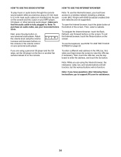
... TO USE THE INTERNET BROWSER To play button on your MP3 player, CD player, or other personal audio player; If you exercise, plug a 3.5 mm male to 3.5 mm male audio cable (not included) into the jack on the console and into a jack on your finger down the screen to support.iFit.com for assistance. 34 make sure that the audio cable is fully plugged...
... TO USE THE INTERNET BROWSER To play button on your MP3 player, CD player, or other personal audio player; If you exercise, plug a 3.5 mm male to 3.5 mm male audio cable (not included) into the jack on the console and into a jack on your finger down the screen to support.iFit.com for assistance. 34 make sure that the audio cable is fully plugged...

English Manual
Page 36
... the power cord. 36 MAINTENANCE AND TROUBLESHOOTING MAINTENANCE Regular maintenance is important for optimal performance and to the correct incline level, see step 5 on page 25. To clean the elliptical, use a damp cloth and a small amount of direct sunlight. CONSOLE TROUBLESHOOTING If the console does not turn on, make sure that the Magnet passes the Reed Switch repeatedly. Inspect and properly tighten all parts each time the elliptical is fully plugged...
... the power cord. 36 MAINTENANCE AND TROUBLESHOOTING MAINTENANCE Regular maintenance is important for optimal performance and to the correct incline level, see step 5 on page 25. To clean the elliptical, use a damp cloth and a small amount of direct sunlight. CONSOLE TROUBLESHOOTING If the console does not turn on, make sure that the Magnet passes the Reed Switch repeatedly. Inspect and properly tighten all parts each time the elliptical is fully plugged...
English Manual
Page 37
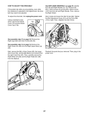
Next, locate and loosen the Idler Screw (89). Then, plug in the power cord. 95 53 20 59 58 37 HOW TO ADJUST THE DRIVE BELT If the pedals slip while you removed. Tighten the Belt Adjustment Screw (91) until the Drive Belt (113) is adjusted to the highest level, the drive belt may need to be adjusted. Then, retighten the Idler Screw. 113 See assembly step 15 on page 14. See assembly step 12 on page 16...
Next, locate and loosen the Idler Screw (89). Then, plug in the power cord. 95 53 20 59 58 37 HOW TO ADJUST THE DRIVE BELT If the pedals slip while you removed. Tighten the Belt Adjustment Screw (91) until the Drive Belt (113) is adjusted to the highest level, the drive belt may need to be adjusted. Then, retighten the Idler Screw. 113 See assembly step 15 on page 14. See assembly step 12 on page 16...
English Manual
Page 38
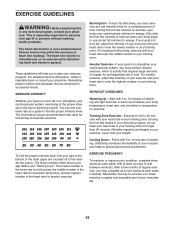
.... The three numbers listed above your age define your breath. Only after the first few weeks of your exercise program, do not keep your heart rate in preparation for prolonged periods of oxygen for exercise. WORKOUT GUIDELINES Warming Up-Start with 5 to find your exercise program. A warm-up to five workouts each week, with pre-existing health problems. The heart rate monitor is the key to plan your...
.... The three numbers listed above your age define your breath. Only after the first few weeks of your exercise program, do not keep your heart rate in preparation for prolonged periods of oxygen for exercise. WORKOUT GUIDELINES Warming Up-Start with 5 to find your exercise program. A warm-up to five workouts each week, with pre-existing health problems. The heart rate monitor is the key to plan your...

English Manual
Page 39
... Cover Incline Motor Incline Motor Arm Ramp Arm Ramp Roller Rear Stabilizer Cover Track Large Frame Bushing Crank Pulley Crank Arm M4 x 10mm Screw Idler M10 x 15mm Screw M10 x 95mm Bolt Resistance Motor M10 x 42mm Bolt Standoff Eddy Mechanism Eddy Mechanism Axle Stabilizer Cap Controller Power Switch Leveling Foot Wheel Pivot Axle Upright Bushing Accessory Tray Reed Switch/Wire Clamp Frame Bearing Small Snap Ring Sleeve Magnet Left Pedal Arm Left Roller Arm Left Upper Body Leg Left Upper Body Arm Hairpin Cotter Pin Left Pedal M10 Locknut Model...
... Cover Incline Motor Incline Motor Arm Ramp Arm Ramp Roller Rear Stabilizer Cover Track Large Frame Bushing Crank Pulley Crank Arm M4 x 10mm Screw Idler M10 x 15mm Screw M10 x 95mm Bolt Resistance Motor M10 x 42mm Bolt Standoff Eddy Mechanism Eddy Mechanism Axle Stabilizer Cap Controller Power Switch Leveling Foot Wheel Pivot Axle Upright Bushing Accessory Tray Reed Switch/Wire Clamp Frame Bearing Small Snap Ring Sleeve Magnet Left Pedal Arm Left Roller Arm Left Upper Body Leg Left Upper Body Arm Hairpin Cotter Pin Left Pedal M10 Locknut Model...

English Manual
Page 40
... x 12mm Screw M10 x 122mm Screw M10 Split Washer Cover Mount M4 x 48mm Screw M6 x 13mm Screw M10 x 60mm Bolt Main Wire #8 x 12mm Screw Grommet Drive Belt M4 x 40mm Screw Controller Bracket Disc Ring Front Upright Cover Shield Cover Cap Power Cord Ramp Axle Small Frame Bushing Clevis Pin 123 1 124 2 125 2 126 2 127 1 128 1 129 1 130 2 131 2 132 2 133 2 134 1 135 8 136 4 137 1 138 1 139 1 140 1 141 2 * - * - * - Key No...
... x 12mm Screw M10 x 122mm Screw M10 Split Washer Cover Mount M4 x 48mm Screw M6 x 13mm Screw M10 x 60mm Bolt Main Wire #8 x 12mm Screw Grommet Drive Belt M4 x 40mm Screw Controller Bracket Disc Ring Front Upright Cover Shield Cover Cap Power Cord Ramp Axle Small Frame Bushing Clevis Pin 123 1 124 2 125 2 126 2 127 1 128 1 129 1 130 2 131 2 132 2 133 2 134 1 135 8 136 4 137 1 138 1 139 1 140 1 141 2 * - * - * - Key No...

English Manual
Page 44
... information when contacting us: • the model number and serial number of the product (see the front cover of this manual) • the name of the product (see the front cover of this manual) • the key number and description of the replacement part(s) (see the PART LIST and the EXPLODED DRAWING near the end of removal or installation; ICON's obligation under this warranty is authorized by ICON. For in-home service...
... information when contacting us: • the model number and serial number of the product (see the front cover of this manual) • the name of the product (see the front cover of this manual) • the key number and description of the replacement part(s) (see the PART LIST and the EXPLODED DRAWING near the end of removal or installation; ICON's obligation under this warranty is authorized by ICON. For in-home service...


