
English Manual
Page 2
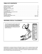
TABLE OF CONTENTS WARNING DECAL PLACEMENT 2 IMPORTANT PRECAUTIONS 3 BEFORE YOU BEGIN 6 PART IDENTIFICATION CHART 7 ASSEMBLY 8 HOW TO USE THE ELLIPTICAL 17 FCC INFORMATION 27 MAINTENANCE AND TROUBLESHOOTING 28 EXERCISE GUIDELINES 30 PART LIST 31 EXPLODED DRAWING 33 ORDERING REPLACEMENT ...a free replacement decal. If a decal is a registered trademark of Google Inc. Note: The decal(s) may not be shown at actual size. NORDICTRACK is missing or illegible, see the front cover of the warning decal(s). Android and Google Play are trademarks of ICON Health & Fitness, Inc. ...
TABLE OF CONTENTS WARNING DECAL PLACEMENT 2 IMPORTANT PRECAUTIONS 3 BEFORE YOU BEGIN 6 PART IDENTIFICATION CHART 7 ASSEMBLY 8 HOW TO USE THE ELLIPTICAL 17 FCC INFORMATION 27 MAINTENANCE AND TROUBLESHOOTING 28 EXERCISE GUIDELINES 30 PART LIST 31 EXPLODED DRAWING 33 ORDERING REPLACEMENT ...a free replacement decal. If a decal is a registered trademark of Google Inc. Note: The decal(s) may not be shown at actual size. NORDICTRACK is missing or illegible, see the front cover of the warning decal(s). Android and Google Play are trademarks of ICON Health & Fitness, Inc. ...

English Manual
Page 7
... the part, from the PART LIST near the end of this manual. Extra parts may be included. Note: If a part is the quantity needed for assembly. The number following the key number is not in parentheses below to see if it has been preassembled. The number in the hardware kit, check...
... the part, from the PART LIST near the end of this manual. Extra parts may be included. Note: If a part is the quantity needed for assembly. The number following the key number is not in parentheses below to see if it has been preassembled. The number in the hardware kit, check...
English Manual
Page 8
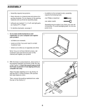
... it from under the rear 2 of the Frame (1). Attach the Rear Stabilizer (2) to the included tool(s), assembly requires the following tools: one Phillips screwdriver one rubber mallet Assembly may be easier if you have Internet access, call Customer Care (see page 7. • In addition to... not dispose of the packing materials until you finish all parts in a cleared area and remove the packing materials. ASSEMBLY • Assembly requires two persons. • Place all assembly steps. • Left parts are marked "L" or "Left" and right parts are marked "R" or "Right." •...
... it from under the rear 2 of the Frame (1). Attach the Rear Stabilizer (2) to the included tool(s), assembly requires the following tools: one Phillips screwdriver one rubber mallet Assembly may be easier if you have Internet access, call Customer Care (see page 7. • In addition to... not dispose of the packing materials until you finish all parts in a cleared area and remove the packing materials. ASSEMBLY • Assembly requires two persons. • Place all assembly steps. • Left parts are marked "L" or "Left" and right parts are marked "R" or "Right." •...
English Manual
Page 29
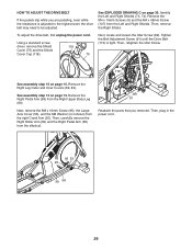
... Belt (113) is adjusted to the highest level, the drive belt may need to be adjusted. See assembly step 12 on page 35. Then, plug in the power cord. 95 53 20 59 58 29 Identify... the Left and Right Shields (73, 74). Then, retighten the Idler Screw. 113 See assembly step 15 on page 15. To adjust the drive belt, first unplug the power cord. Next, remove the ...M8 x 16mm Screw (95), the Large Axle Cover (53), and the M8 Washer (not shown) from the elliptical. 89 91 Reattach the parts that you are pedaling, even while the resistance is tight. Then, carefully remove the ...
... Belt (113) is adjusted to the highest level, the drive belt may need to be adjusted. See assembly step 12 on page 35. Then, plug in the power cord. 95 53 20 59 58 29 Identify... the Left and Right Shields (73, 74). Then, retighten the Idler Screw. 113 See assembly step 15 on page 15. To adjust the drive belt, first unplug the power cord. Next, remove the ...M8 x 16mm Screw (95), the Large Axle Cover (53), and the M8 Washer (not shown) from the elliptical. 89 91 Reattach the parts that you are pedaling, even while the resistance is tight. Then, carefully remove the ...
English Manual
Page 31
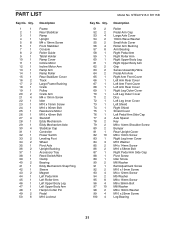
... Washer Small Axle Cover Roller Arm Bushing Arm Bearing Right Pedal Arm Right Roller Arm Right Upper Body Leg Right Upper Body Arm Grip Sensor Assembly/Wire Pedal Arm Axle Right Arm Front Cover Left Arm Rear Cover Left Arm Front Cover Left Arm Rear Cover Right Leg Outer Cover Left...
... Washer Small Axle Cover Roller Arm Bushing Arm Bearing Right Pedal Arm Right Roller Arm Right Upper Body Leg Right Upper Body Arm Grip Sensor Assembly/Wire Pedal Arm Axle Right Arm Front Cover Left Arm Rear Cover Left Arm Front Cover Left Arm Rear Cover Right Leg Outer Cover Left...

English Manual
Page 32
Qty. Front Upright Cover Shield Cover Cap Power Cord Ramp Axle Small Frame Bushing Clevis Pin Plastic Spacer M4 x 19mm Self-tapping Screw Assembly Tool Grease Packet User's Manual Incline Motor Wire Resistance Motor Wire Blue Wire Green Wire White Wire Note: Specifications are not illustrated. 32 Qty. For ...
Qty. Front Upright Cover Shield Cover Cap Power Cord Ramp Axle Small Frame Bushing Clevis Pin Plastic Spacer M4 x 19mm Self-tapping Screw Assembly Tool Grease Packet User's Manual Incline Motor Wire Resistance Motor Wire Blue Wire Green Wire White Wire Note: Specifications are not illustrated. 32 Qty. For ...


