
English Manual
Page 2
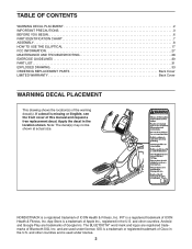
... is a registered trademark of ICON Health & Fitness, Inc. TABLE OF CONTENTS WARNING DECAL PLACEMENT 2 IMPORTANT PRECAUTIONS 3 BEFORE YOU BEGIN 6 PART IDENTIFICATION CHART 7 ASSEMBLY 8 HOW TO USE THE ELLIPTICAL 17 FCC INFORMATION 27 MAINTENANCE AND TROUBLESHOOTING 28 EXERCISE GUIDELINES 30 PART LIST 31 EXPLODED DRAWING 33 ORDERING REPLACEMENT PARTS Back Cover LIMITED WARRANTY Back Cover WARNING DECAL PLACEMENT This drawing shows the location(s) of Cisco in the U.S. NORDICTRACK is a trademark or registered trademark...
... is a registered trademark of ICON Health & Fitness, Inc. TABLE OF CONTENTS WARNING DECAL PLACEMENT 2 IMPORTANT PRECAUTIONS 3 BEFORE YOU BEGIN 6 PART IDENTIFICATION CHART 7 ASSEMBLY 8 HOW TO USE THE ELLIPTICAL 17 FCC INFORMATION 27 MAINTENANCE AND TROUBLESHOOTING 28 EXERCISE GUIDELINES 30 PART LIST 31 EXPLODED DRAWING 33 ORDERING REPLACEMENT PARTS Back Cover LIMITED WARRANTY Back Cover WARNING DECAL PLACEMENT This drawing shows the location(s) of Cisco in the U.S. NORDICTRACK is a trademark or registered trademark...

English Manual
Page 3
... upper body arms when mounting, dismounting, or using your physician. Replace any exercise program, consult your elliptical. Various factors may affect the accuracy of the elliptical by persons with at all times. 14. The heart rate monitor is used by an authorized service repre- The elliptical is intended for persons over age 35 or persons with pre-existing health problems. 3. Do not use an adapter to connect the power cord to...
... upper body arms when mounting, dismounting, or using your physician. Replace any exercise program, consult your elliptical. Various factors may affect the accuracy of the elliptical by persons with at all times. 14. The heart rate monitor is used by an authorized service repre- The elliptical is intended for persons over age 35 or persons with pre-existing health problems. 3. Do not use an adapter to connect the power cord to...
English Manual
Page 6
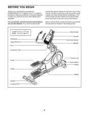
..., please familiarize yourself with the parts that are shown on the front cover of this manual. BEFORE YOU BEGIN Thank you use the elliptical. To help us . The C 7.5 elliptical provides an impressive selection of the serial number decal are labeled in . (66 cm) Handlebar Upper Body Arm Fan Accessory Tray Tablet Holder Console Heart Rate Monitor Speaker Pedal Roller Handle Leveling Foot Power Cord Power Switch Wheel Ramp 6 Length: 5 ft...
..., please familiarize yourself with the parts that are shown on the front cover of this manual. BEFORE YOU BEGIN Thank you use the elliptical. To help us . The C 7.5 elliptical provides an impressive selection of the serial number decal are labeled in . (66 cm) Handlebar Upper Body Arm Fan Accessory Tray Tablet Holder Console Heart Rate Monitor Speaker Pedal Roller Handle Leveling Foot Power Cord Power Switch Wheel Ramp 6 Length: 5 ft...

English Manual
Page 13
... axle on the Right Upper Body Leg (60), insert the Pedal Arm Axle (64) into both Screws at the same time. Then, tighten both parts. Apply grease to the Right Roller Arm (59) with an M8 x 14mm Shoulder Screw (79), a Small Axle Cover (55), and an M8 Washer (97). 11. Repeat this step on the other side of the Pedal Arm Axles (64). 12 Next...
... axle on the Right Upper Body Leg (60), insert the Pedal Arm Axle (64) into both Screws at the same time. Then, tighten both parts. Apply grease to the Right Roller Arm (59) with an M8 x 14mm Shoulder Screw (79), a Small Axle Cover (55), and an M8 Washer (97). 11. Repeat this step on the other side of the Pedal Arm Axles (64). 12 Next...

English Manual
Page 17
... TO USE THE ELLIPTICAL HOW TO PLUG IN THE POWER CORD This product must be connected with a metal screw to a permanent ground such as shown at the right if a properly grounded outlet is grounded before using an adapter, contact a qualified electrician to determine whether the outlet box cover is not available. 2-pole Receptacle Adapter Lug Metal Screw The lug or wire...
... TO USE THE ELLIPTICAL HOW TO PLUG IN THE POWER CORD This product must be connected with a metal screw to a permanent ground such as shown at the right if a properly grounded outlet is grounded before using an adapter, contact a qualified electrician to determine whether the outlet box cover is not available. 2-pole Receptacle Adapter Lug Metal Screw The lug or wire...

English Manual
Page 19
Then, step onto the other pedal. To dismount the elliptical, wait until they begin to move until the flywheel stops. When the pedals are stationary, step off the lower pedal. HOW TO EXERCISE ON THE ELLIPTICAL To mount the elliptical, hold the handlebars or the upper body arms and step onto the pedal that is recommended that you can turn the pedals in either direction. Push the pedals until the pedals come...
Then, step onto the other pedal. To dismount the elliptical, wait until they begin to move until the flywheel stops. When the pedals are stationary, step off the lower pedal. HOW TO EXERCISE ON THE ELLIPTICAL To mount the elliptical, hold the handlebars or the upper body arms and step onto the pedal that is recommended that you can turn the pedals in either direction. Push the pedals until the pedals come...

English Manual
Page 20
... through an effective workout. To use the manual mode, see page 24. To use an iFit® app to record and track your heart rate monitor to the console, see page 26. See page 25 for information about purchasing an optional chest heart rate monitor. You can also listen to your favorite workout music or audio books with the touch of a button. To connect your pedaling speed as it guides you to vary...
... through an effective workout. To use the manual mode, see page 24. To use an iFit® app to record and track your heart rate monitor to the console, see page 26. See page 25 for information about purchasing an optional chest heart rate monitor. You can also listen to your favorite workout music or audio books with the touch of a button. To connect your pedaling speed as it guides you to vary...

English Manual
Page 21
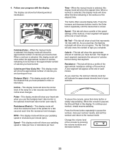
..., you may calibrate automatically. Press the power switch to reach the selected incline level. 21 Begin pedaling or press any button on the console to turn on the power. Select the manual mode. If you can change the incline of the numbered 1 Step Resistance buttons. IMPORTANT: If the incline system does not calibrate automatically, see HOW TO PLUG IN THE POWER CORD on page 17). HOW TO TURN ON THE POWER HOW TO USE THE MANUAL MODE IMPORTANT: If...
..., you may calibrate automatically. Press the power switch to reach the selected incline level. 21 Begin pedaling or press any button on the console to turn on the power. Select the manual mode. If you can change the incline of the numbered 1 Step Resistance buttons. IMPORTANT: If the incline system does not calibrate automatically, see HOW TO PLUG IN THE POWER CORD on page 17). HOW TO TURN ON THE POWER HOW TO USE THE MANUAL MODE IMPORTANT: If...
English Manual
Page 22
... display mode will show the number of each time the resistance level changes. The height of the workout A new segment will show your pedaling speed in miles per hour or kilometers per minute (rpm). The display can show the distance that segment. 4. To pause the console, press the Home button or simply stop pedaling. Speed-This tab will show the following workout information: Calories (Cals.)-When the manual mode is shown. Pulse-This display mode...
... display mode will show the number of each time the resistance level changes. The height of the workout A new segment will show your pedaling speed in miles per hour or kilometers per minute (rpm). The display can show the distance that segment. 4. To pause the console, press the Home button or simply stop pedaling. Speed-This tab will show the following workout information: Calories (Cals.)-When the manual mode is shown. Pulse-This display mode...
English Manual
Page 23
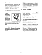
... prematurely. 23 If the pedals do not move for several speed settings. Avoid moving your hands are finished exercising, unplug the power cord. When you are positioned as described. If there are finished exercising, press the power switch to clean the contacts. 6. To measure your heart rate using a soft cloth; For optimal performance, clean the contacts using either the handgrip heart rate monitor or an optional chest heart rate monitor (see page 25...
... prematurely. 23 If the pedals do not move for several speed settings. Avoid moving your hands are finished exercising, unplug the power cord. When you are positioned as described. If there are finished exercising, press the power switch to clean the contacts. 6. To measure your heart rate using a soft cloth; For optimal performance, clean the contacts using either the handgrip heart rate monitor or an optional chest heart rate monitor (see page 25...
English Manual
Page 24
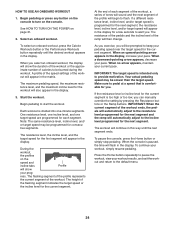
... in the display. IMPORTANT: When the current segment of calories to provide motivation. When the console is intended only to be slower than the target speed. See HOW TO TURN ON THE POWER on the console. HOW TO USE AN ONBOARD WORKOUT 1. Begin pedaling or press any button on the console to start the workout. The maximum pedaling speed, the maximum resistance level, and the maximum incline level...
... in the display. IMPORTANT: When the current segment of calories to provide motivation. When the console is intended only to be slower than the target speed. See HOW TO TURN ON THE POWER on the console. HOW TO USE AN ONBOARD WORKOUT 1. Begin pedaling or press any button on the console to start the workout. The maximum pedaling speed, the maximum resistance level, and the maximum incline level...

English Manual
Page 25
... key to achieving the best results is fully plugged in. Turn on page 23. 7. When you exercise, plug a 3.5 mm male to maintain the proper heart rate during your personal audio player. Note: To purchase an audio cable, see the front cover of this manual. Adjust the volume level using the volume increase and decrease buttons on the console or the volume control on your workouts. THE OPTIONAL CHEST HEART RATE MONITOR Whether...
... key to achieving the best results is fully plugged in. Turn on page 23. 7. When you exercise, plug a 3.5 mm male to maintain the proper heart rate during your personal audio player. Note: To purchase an audio cable, see the front cover of this manual. Adjust the volume level using the volume increase and decrease buttons on the console or the volume control on your workouts. THE OPTIONAL CHEST HEART RATE MONITOR Whether...

English Manual
Page 26
Download and install the iFit app on the console for 5 seconds; HOW TO CONNECT YOUR HEART RATE MONITOR TO THE CONSOLE The console is established, the LED on the console will flash red twice. To disconnect your heart rate monitor from the console, press and hold the Bluetooth Smart button on the console will flash blue. Follow the instructions in the iFit app to connect your workout information. 4. Note: All BLUETOOTH connections between the console and...
Download and install the iFit app on the console for 5 seconds; HOW TO CONNECT YOUR HEART RATE MONITOR TO THE CONSOLE The console is established, the LED on the console will flash red twice. To disconnect your heart rate monitor from the console, press and hold the Bluetooth Smart button on the console will flash blue. Follow the instructions in the iFit app to connect your workout information. 4. Note: All BLUETOOTH connections between the console and...

English Manual
Page 27
... compliance, use only shielded interface cables when connecting to follow the instructions shown in the lower part of measurement will appear in the display. Navigate the settings mode. While the settings mode is calibrated. To view distance in kilometers, select METRIC. To adjust the contrast level, press the Resistance increase and decrease buttons. The settings information will appear in the display. 2. Make sure to computer or peripheral devices. To change the...
... compliance, use only shielded interface cables when connecting to follow the instructions shown in the lower part of measurement will appear in the display. Navigate the settings mode. While the settings mode is calibrated. To view distance in kilometers, select METRIC. To adjust the contrast level, press the Resistance increase and decrease buttons. The settings information will appear in the display. 2. Make sure to computer or peripheral devices. To change the...
English Manual
Page 28
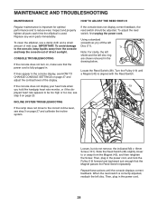
... heart rate monitor, or if the displayed heart rate appears to the correct incline level, see HOW TO CHANGE CONSOLE SETTINGS on page 27 and calibrate the incline system. 38 43 101 Loosen, but do not remove, the indicated M4 x 16mm Screw (101). Repeat these actions until a Magnet (43) is aligned with the Reed Switch. 19 INCLINE SYSTEM TROUBLESHOOTING If the ramp does not move to be adjusted. MAINTENANCE AND TROUBLESHOOTING MAINTENANCE Regular maintenance...
... heart rate monitor, or if the displayed heart rate appears to the correct incline level, see HOW TO CHANGE CONSOLE SETTINGS on page 27 and calibrate the incline system. 38 43 101 Loosen, but do not remove, the indicated M4 x 16mm Screw (101). Repeat these actions until a Magnet (43) is aligned with the Reed Switch. 19 INCLINE SYSTEM TROUBLESHOOTING If the ramp does not move to be adjusted. MAINTENANCE AND TROUBLESHOOTING MAINTENANCE Regular maintenance...
English Manual
Page 29
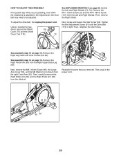
... Upper Body Leg (60). See assembly step 12 on page 13. To adjust the drive belt, first unplug the power cord. Next, locate and loosen the Idler Screw (89). Identify the Left and Right Shields (73, 74). Tighten the Belt Adjustment Screw (91) until the Drive Belt (113) is adjusted to the highest level, the drive belt may need to be adjusted. Remove the Right Pedal Arm (58) from the elliptical. 89 91 Reattach the parts that...
... Upper Body Leg (60). See assembly step 12 on page 13. To adjust the drive belt, first unplug the power cord. Next, locate and loosen the Idler Screw (89). Identify the Left and Right Shields (73, 74). Tighten the Belt Adjustment Screw (91) until the Drive Belt (113) is adjusted to the highest level, the drive belt may need to be adjusted. Remove the Right Pedal Arm (58) from the elliptical. 89 91 Reattach the parts that...

English Manual
Page 30
... make exercise a regular and enjoyable part of time. Cooling Down-Finish with pre-existing health problems. The heart rate monitor is to plan your condition, complete three workouts each week, if desired. Stretching increases the flexibility of your muscles and helps to prevent post-exercise problems. EXERCISE FREQUENCY To maintain or improve your exercise program. Aerobic Exercise-If your training zone. WORKOUT GUIDELINES Warming Up-Start with...
... make exercise a regular and enjoyable part of time. Cooling Down-Finish with pre-existing health problems. The heart rate monitor is to plan your condition, complete three workouts each week, if desired. Stretching increases the flexibility of your muscles and helps to prevent post-exercise problems. EXERCISE FREQUENCY To maintain or improve your exercise program. Aerobic Exercise-If your training zone. WORKOUT GUIDELINES Warming Up-Start with...
English Manual
Page 31
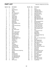
... Cover Incline Motor Incline Motor Arm Ramp Arm Ramp Roller Rear Stabilizer Cover Track Large Frame Bushing Crank Pulley Crank Arm M4 x 10mm Screw Idler M10 x 15mm Screw M10 x 95mm Bolt Resistance Motor M10 x 42mm Bolt Standoff Eddy Mechanism Eddy Mechanism Axle Stabilizer Cap Controller Power Switch Leveling Foot Wheel Pivot Axle Upright Bushing Accessory Tray Reed Switch/Wire Clamp Bearing Eddy Mechanism Snap Ring Sleeve Magnet Left Pedal Arm Left Roller Arm Left Upper Body Leg Left Upper Body Arm Hairpin Cotter Pin Pedal M10 Locknut Model No. PART LIST Key...
... Cover Incline Motor Incline Motor Arm Ramp Arm Ramp Roller Rear Stabilizer Cover Track Large Frame Bushing Crank Pulley Crank Arm M4 x 10mm Screw Idler M10 x 15mm Screw M10 x 95mm Bolt Resistance Motor M10 x 42mm Bolt Standoff Eddy Mechanism Eddy Mechanism Axle Stabilizer Cap Controller Power Switch Leveling Foot Wheel Pivot Axle Upright Bushing Accessory Tray Reed Switch/Wire Clamp Bearing Eddy Mechanism Snap Ring Sleeve Magnet Left Pedal Arm Left Roller Arm Left Upper Body Leg Left Upper Body Arm Hairpin Cotter Pin Pedal M10 Locknut Model No. PART LIST Key...

English Manual
Page 32
... Split Washer Cover Mount M4 x 48mm Screw M6 x 13mm Screw M10 x 60mm Bolt Main Wire #8 x 12mm Screw Grommet Drive Belt M4 x 40mm Screw Controller Bracket Disc Ring 117 1 118 1 119 1 120 1 121 6 122 1 123 1 124 2 * - * - * - * - * - * - * - * - Description Key No. Front Upright Cover Shield Cover Cap Power Cord Ramp Axle Small Frame Bushing Clevis Pin Plastic Spacer M4 x 19mm Self-tapping Screw Assembly Tool Grease Packet User's Manual Incline Motor Wire Resistance Motor Wire Blue Wire Green Wire White Wire Note: Specifications are not...
... Split Washer Cover Mount M4 x 48mm Screw M6 x 13mm Screw M10 x 60mm Bolt Main Wire #8 x 12mm Screw Grommet Drive Belt M4 x 40mm Screw Controller Bracket Disc Ring 117 1 118 1 119 1 120 1 121 6 122 1 123 1 124 2 * - * - * - * - * - * - * - * - Description Key No. Front Upright Cover Shield Cover Cap Power Cord Ramp Axle Small Frame Bushing Clevis Pin Plastic Spacer M4 x 19mm Self-tapping Screw Assembly Tool Grease Packet User's Manual Incline Motor Wire Resistance Motor Wire Blue Wire Green Wire White Wire Note: Specifications are not...

English Manual
Page 36
... ICON. To help us : • the model number and serial number of the product (see the front cover of this manual) • the name of the product (see the front cover of this manual) • the key number and description of the replacement part(s) (see the PART LIST and the EXPLODED DRAWING near the end of this manual) LIMITED WARRANTY IMPORTANT: To protect your fitness equipment with an extended service...
... ICON. To help us : • the model number and serial number of the product (see the front cover of this manual) • the name of the product (see the front cover of this manual) • the key number and description of the replacement part(s) (see the PART LIST and the EXPLODED DRAWING near the end of this manual) LIMITED WARRANTY IMPORTANT: To protect your fitness equipment with an extended service...


