
English Manual
Page 1
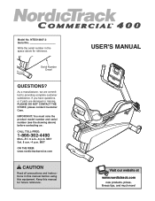
... precautions and instructions in the space above ) before using this manual for reference. Serial Number Decal QUESTIONS? IMPORTANT: You must note the product model number and serial number (see the drawing above for future reference. MST Sat. 8 a.m.-4 p.m. USER'S MANUAL Visit our website at www.nordictrack.com new products, prizes, fitness tips, and much more! NTEX14807.2 Serial No. If you have questions, or if parts are committed...
... precautions and instructions in the space above ) before using this manual for reference. Serial Number Decal QUESTIONS? IMPORTANT: You must note the product model number and serial number (see the drawing above for future reference. MST Sat. 8 a.m.-4 p.m. USER'S MANUAL Visit our website at www.nordictrack.com new products, prizes, fitness tips, and much more! NTEX14807.2 Serial No. If you have questions, or if parts are committed...
English Manual
Page 2
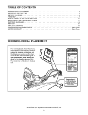
... 4 ASSEMBLY 5 HOW TO OPERATE THE EXERCISE CYCLE 11 MAINTENANCE AND TROUBLESHOOTING 17 EXERCISE GUIDELINES 18 PART LIST 21 EXPLODED DRAWING 22 ORDERING REPLACEMENT PARTS Back Cover LIMITED WARRANTY Back Cover WARNING DECAL PLACEMENT The warning decals shown here have been applied in the location shown. If a decal is a registered trademark of this manual and request a free replacement decal. Note: The decal may not be shown at actual size...
... 4 ASSEMBLY 5 HOW TO OPERATE THE EXERCISE CYCLE 11 MAINTENANCE AND TROUBLESHOOTING 17 EXERCISE GUIDELINES 18 PART LIST 21 EXPLODED DRAWING 22 ORDERING REPLACEMENT PARTS Back Cover LIMITED WARRANTY Back Cover WARNING DECAL PLACEMENT The warning decals shown here have been applied in the location shown. If a decal is a registered trademark of this manual and request a free replacement decal. Note: The decal may not be shown at actual size...

English Manual
Page 3
... down. 13. Replace any exercise program, consult your physician. When you feel pain or dizziness while exercising, stop . 12. Keep your exercise cycle indoors, away from your exercise cycle. If you stop exercising, allow the pedals to slowly come to protect the floor or carpet. Always wear athletic shoes for home use of heart rate readings. Make sure that all users of the exercise cycle are...
... down. 13. Replace any exercise program, consult your physician. When you feel pain or dizziness while exercising, stop . 12. Keep your exercise cycle indoors, away from your exercise cycle. If you stop exercising, allow the pedals to slowly come to protect the floor or carpet. Always wear athletic shoes for home use of heart rate readings. Make sure that all users of the exercise cycle are...
English Manual
Page 4
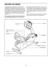
... see the front cover of the most effective exercises for selecting the new NordicTrack Commercial™ 400 exercise cycle. For your home. Handlebar Console Adjustment Handle Seat Backrest Pedal/Strap Handle Leveling Foot Wheel Handgrip Pulse Sensor Seat Handlebar 4 BEFORE YOU BEGIN Congratulations for increasing cardiovascular fitness, building endurance, and toning the entire body. If you , note the product model number and serial number before you enjoy this healthful exercise in the...
... see the front cover of the most effective exercises for selecting the new NordicTrack Commercial™ 400 exercise cycle. For your home. Handlebar Console Adjustment Handle Seat Backrest Pedal/Strap Handle Leveling Foot Wheel Handgrip Pulse Sensor Seat Handlebar 4 BEFORE YOU BEGIN Congratulations for increasing cardiovascular fitness, building endurance, and toning the entire body. If you , note the product model number and serial number before you enjoy this healthful exercise in the...
English Manual
Page 5
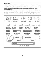
... parts used in parentheses below to see if it has been preattached. Place all parts of the packing materials until assembly is the key number of the part, from the PART LIST near the end of this manual. Assembly requires the included tools and your own adjustable wrench screwdriver . The number in assembly. Note: Some small parts may have been preattached. If a part is the quantity needed...
... parts used in parentheses below to see if it has been preattached. Place all parts of the packing materials until assembly is the key number of the part, from the PART LIST near the end of this manual. Assembly requires the included tools and your own adjustable wrench screwdriver . The number in assembly. Note: Some small parts may have been preattached. If a part is the quantity needed...

English Manual
Page 6
... 65 91 16 91 1 3. While another person lifts the rear of the Frame (1), attach the Rear Stabilizer (16) to attach the other Backrest Tube (52). 52 41 52 93 72 99 6 Attach the Backrest Tube with two M10 x 94mm Button Bolts (65), two M10 Curved Washers (94), and two M10... this step to the Frame with the Wheels (17) positioned as shown. Attach the Front Stabilizer to the Frame (1) with an M8 x 35mm Button Bolt (72), an M8 Split Washer (93), and an M8 Nylon Locknut (99). Do not tighten the Button Bolt yet. To make assembly easier, read the 1 information on the Seat Carriage...
... 65 91 16 91 1 3. While another person lifts the rear of the Frame (1), attach the Rear Stabilizer (16) to attach the other Backrest Tube (52). 52 41 52 93 72 99 6 Attach the Backrest Tube with two M10 x 94mm Button Bolts (65), two M10 Curved Washers (94), and two M10... this step to the Frame with the Wheels (17) positioned as shown. Attach the Front Stabilizer to the Frame (1) with an M8 x 35mm Button Bolt (72), an M8 Split Washer (93), and an M8 Nylon Locknut (99). Do not tighten the Button Bolt yet. To make assembly easier, read the 1 information on the Seat Carriage...

English Manual
Page 7
Tip: Avoid damaging the wires inside the Seat Handlebar (11) during this step. Then, plug the Lower Pulse Wire (58) into the receptacle in the Seat Carriage. Tighten the two M8 x 35mm Button Bolts (72). 5 11 86 99 41 70 86 58 99 14 7 Attach the Seat Handlebar (11) to the Backrest Tubes (52) with two M8 x 68mm Button Bolts (70), two M8 Curved Washers (86...
Tip: Avoid damaging the wires inside the Seat Handlebar (11) during this step. Then, plug the Lower Pulse Wire (58) into the receptacle in the Seat Carriage. Tighten the two M8 x 35mm Button Bolts (72). 5 11 86 99 41 70 86 58 99 14 7 Attach the Seat Handlebar (11) to the Backrest Tubes (52) with two M8 x 68mm Button Bolts (70), two M8 Curved Washers (86...

English Manual
Page 8
Attach the Book Holder (3) to the Backrest (8) with two M4 x 38mm Screws (89). 3 8 52 75 89 7. 6. Then, attach the Book Holder to the Backrest Tubes 6 (52) with four M6 x 16mm Button Screws (71) and four M6 Washers (88). Orient the Seat (9) as shown. Attach the Seat to the 7 Seat Carriage (41) with two M4 x 19mm Screws (75). Note: Only 9 two Screws and two Washers are shown. 41 88 88 71 8
Attach the Book Holder (3) to the Backrest (8) with two M4 x 38mm Screws (89). 3 8 52 75 89 7. 6. Then, attach the Book Holder to the Backrest Tubes 6 (52) with four M6 x 16mm Button Screws (71) and four M6 Washers (88). Orient the Seat (9) as shown. Attach the Seat to the 7 Seat Carriage (41) with two M4 x 19mm Screws (75). Note: Only 9 two Screws and two Washers are shown. 41 88 88 71 8

English Manual
Page 9
... until step 10. Tie the lower end of tape or an elastic band to hold the Upright (2) near the Upright (2), connect the console wire to the Upright (2) with four M4 x 16mm Round Head Screws (68). 10 Pulse Wire 42 61 43 4 Console Ground Wire Wire 68 68 2 9 Use a piece of the wire tie to the Main Wire Harness (43) and to fall into the Upright (2). Tip: Tighten the two Button Screws...
... until step 10. Tie the lower end of tape or an elastic band to hold the Upright (2) near the Upright (2), connect the console wire to the Upright (2) with four M4 x 16mm Round Head Screws (68). 10 Pulse Wire 42 61 43 4 Console Ground Wire Wire 68 68 2 9 Use a piece of the wire tie to the Main Wire Harness (43) and to fall into the Upright (2). Tip: Tighten the two Button Screws...

English Manual
Page 10
... Bottom Handlebar Cover (53) into the Right Crank Arm (23). Using an adjustable wrench, firmly tighten the Right Pedal clockwise into the 11 slots on the underside of the Console (4). Make sure that all parts are properly tightened before plugging in the same way. 23 Strap 21 Tab 13. Plug the power supply into the Left Crank Arm (not shown). Then, attach the Bottom Handlebar Cover and the...
... Bottom Handlebar Cover (53) into the Right Crank Arm (23). Using an adjustable wrench, firmly tighten the Right Pedal clockwise into the 11 slots on the underside of the Console (4). Make sure that all parts are properly tightened before plugging in the same way. 23 Strap 21 Tab 13. Plug the power supply into the Left Crank Arm (not shown). Then, attach the Bottom Handlebar Cover and the...

English Manual
Page 11
... Plug one or both of the leveling feet under the rear stabilizer until the exercise cycle can be moved on your floor during use, turn one end of the included power supply into an appropriate outlet that is properly installed in place. Pedal Strap Tab HOW TO ADJUST THE SEAT The seat can be adjusted forward or backward to the desired position, and then press...
... Plug one or both of the leveling feet under the rear stabilizer until the exercise cycle can be moved on your floor during use, turn one end of the included power supply into an appropriate outlet that is properly installed in place. Pedal Strap Tab HOW TO ADJUST THE SEAT The seat can be adjusted forward or backward to the desired position, and then press...

English Manual
Page 12
... effective workout. You can change the resistance of the pedals with the touch of a button. Each workout automatically changes the resistance of the console, you can even measure your pedaling pace as it guides you exercise, the console will provide continuous exercise feedback. To use a preset workout, see page 16. When you select the manual mode of the pedals and prompts you to increase or decrease your heart rate using the handgrip pulse sensor.
... effective workout. You can change the resistance of the pedals with the touch of a button. Each workout automatically changes the resistance of the console, you can even measure your pedaling pace as it guides you exercise, the console will provide continuous exercise feedback. To use a preset workout, see page 16. When you select the manual mode of the pedals and prompts you to increase or decrease your heart rate using the handgrip pulse sensor.
English Manual
Page 13
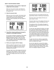
... time, distance, approximate number of resistance levels and pedaling pace. First, press and hold down the Display button for a few seconds each time the resistance level changes. Then, release the Display button and follow the instructions in the display. 3. When you turn on the console, the manual mode will show your heart rate when you use . 2. When you pedal, the upper left corner of the pedals by pressing the Workouts button repeatedly until the display is...
... time, distance, approximate number of resistance levels and pedaling pace. First, press and hold down the Display button for a few seconds each time the resistance level changes. Then, release the Display button and follow the instructions in the display. 3. When you turn on the console, the manual mode will show your heart rate when you use . 2. When you pedal, the upper left corner of the pedals by pressing the Workouts button repeatedly until the display is...

English Manual
Page 14
... the fan at low speed, press the Fan button a second time. If there are not moved for at least 15 seconds. To turn on the handgrip pulse sensor, remove the plas- If the pedals are sheets of tones will sound and the console will automatically turn off automatically. 5. To measure your heart rate, hold the contacts for several seconds, a series of clear Contacts plastic...
... the fan at low speed, press the Fan button a second time. If there are not moved for at least 15 seconds. To turn on the handgrip pulse sensor, remove the plas- If the pedals are sheets of tones will sound and the console will automatically turn off automatically. 5. To measure your heart rate, hold the contacts for several seconds, a series of clear Contacts plastic...
English Manual
Page 15
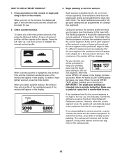
... SPEED UP appear in the display. Make sure to alert you turn on the console. To restart the workout, press Start or simply resume pedaling. The flashing segment of the profile represents the current segment of workout profiles will then change. If a different resistance level is programmed for the next segment, the resistance level will automatically adjust to the resistance level for a few seconds to pedal...
... SPEED UP appear in the display. Make sure to alert you turn on the console. To restart the workout, press Start or simply resume pedaling. The flashing segment of the profile represents the current segment of workout profiles will then change. If a different resistance level is programmed for the next segment, the resistance level will automatically adjust to the resistance level for a few seconds to pedal...

English Manual
Page 16
... music or audio books through the console's stereo sound system while you exercise, first locate the Cable stereo audio cable in watts, and pedaling pace, press the Display button again. Plug the cable into the storage recess on the fan if desired. To view the time remaining, distance pedaled, approximate number of calories burned. Measure your power output in the center of the speakers using the volume control on your...
... music or audio books through the console's stereo sound system while you exercise, first locate the Cable stereo audio cable in watts, and pedaling pace, press the Display button again. Plug the cable into the storage recess on the fan if desired. To view the time remaining, distance pedaled, approximate number of calories burned. Measure your power output in the center of the speakers using the volume control on your...
English Manual
Page 17
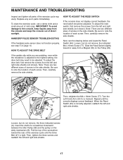
... the console does not display correct feedback, the reed switch should be adjusted. Slide the Reed Switch slightly toward the rear of direct sunlight. Turn the Left Crank Arm (24) for a moment. Repeat until the Drive Belt (47) is adjusted to the highest setting, the drive belt may need to the console, keep the console out of the exercise cycle until the console displays correct feedback. A Loosen, but do not remove, the three indicated screws (A). Then, tighten...
... the console does not display correct feedback, the reed switch should be adjusted. Slide the Reed Switch slightly toward the rear of direct sunlight. Turn the Left Crank Arm (24) for a moment. Repeat until the Drive Belt (47) is adjusted to the highest setting, the drive belt may need to the console, keep the console out of the exercise cycle until the console displays correct feedback. A Loosen, but do not remove, the three indicated screws (A). Then, tighten...

English Manual
Page 18
... your heart rate as an exercise aid in determining heart rate trends in your body uses carbohydrate calories for energy. Cooling down-Finish with pre-existing health problems. The pulse sensor is activity that requires large amounts of oxygen for prolonged periods of time. Various factors may complete up -Start with at the bottom of the chart (ages are essential for aerobic exercise. The pulse sensor...
... your heart rate as an exercise aid in determining heart rate trends in your body uses carbohydrate calories for energy. Cooling down-Finish with pre-existing health problems. The pulse sensor is activity that requires large amounts of oxygen for prolonged periods of time. Various factors may complete up -Start with at the bottom of the chart (ages are essential for aerobic exercise. The pulse sensor...
English Manual
Page 21
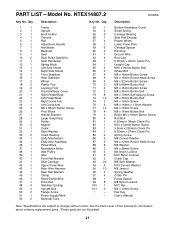
... Pedal/Strap Left Pedal/Strap Right Crank Arm Left Crank Arm M6 x 38mm Button Screw Pivot Block Handle Bracket Large Snap Ring Pulley Magnet Crank Steel Washer Crank Bearing Eddy Mechanism Eddy Axle Assembly Pillow Block Resistance Motor Idler Pulley Idler Front Rail Bracket Seat Carriage Upper Pulse Wire Main Wire Harness Rear Rail Bracket Clamp Reed Switch/Wire Drive Belt Stabilizer Endcap Upright Grip Flange Screw Power Supply/Wire Backrest Tube Key No. See the back cover of this manual for information about ordering replacement parts...
... Pedal/Strap Left Pedal/Strap Right Crank Arm Left Crank Arm M6 x 38mm Button Screw Pivot Block Handle Bracket Large Snap Ring Pulley Magnet Crank Steel Washer Crank Bearing Eddy Mechanism Eddy Axle Assembly Pillow Block Resistance Motor Idler Pulley Idler Front Rail Bracket Seat Carriage Upper Pulse Wire Main Wire Harness Rear Rail Bracket Clamp Reed Switch/Wire Drive Belt Stabilizer Endcap Upright Grip Flange Screw Power Supply/Wire Backrest Tube Key No. See the back cover of this manual for information about ordering replacement parts...

English Manual
Page 24
ORDERING REPLACEMENT PARTS To order replacement parts, please see the PART LIST and the EXPLODED DRAWING near the end of this manual) LIMITED WARRANTY ICON Health & Fitness, Inc. (ICON) warrants this product to be free from defects in workmanship and material, under this warranty is limited in -home service, the customer will be responsible for which vary from state to and from the date of whatsoever nature. There is...
ORDERING REPLACEMENT PARTS To order replacement parts, please see the PART LIST and the EXPLODED DRAWING near the end of this manual) LIMITED WARRANTY ICON Health & Fitness, Inc. (ICON) warrants this product to be free from defects in workmanship and material, under this warranty is limited in -home service, the customer will be responsible for which vary from state to and from the date of whatsoever nature. There is...


