Repair Manual
Page 1
Lite:Touch FCA45001 ZOOM120 ED FCA45201 FCA45211 FCA45221 REPAIR MANUAL Nikon NIKON CORPORATION I Tokyo, Japan Printed in Japan June 2000 Copyright © 2000 by Nikon Corporation All Rights Reserved. A i'MY*gg fd EP 0,1(1 C S iff;E; G. R. 3498. FCA45001 -
Lite:Touch FCA45001 ZOOM120 ED FCA45201 FCA45211 FCA45221 REPAIR MANUAL Nikon NIKON CORPORATION I Tokyo, Japan Printed in Japan June 2000 Copyright © 2000 by Nikon Corporation All Rights Reserved. A i'MY*gg fd EP 0,1(1 C S iff;E; G. R. 3498. FCA45001 -
Repair Manual
Page 3
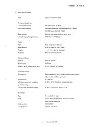
... - Main specifications Type Photographing lens Lens focal distance Lens configuration Zoom system Lens photographing distance Finder Type Magnification Diopter Eyepiece Automatic focus System Base length Number of AF (Auto focus) step Exposure control Shutter type Shutter time AE (Auto exposure) coupling operation range FM coupling operation range Speed light Type Mode Guide number Charging time Camera for 35mm film f38-120mm/F5.3-10.5 3 groups zoom type and 5 groups with 7 lenses (Gl: ED lens, G5, G6: PGM) Electric step zoom system and 6 steps W: 0.75m- FCA45001 - M1 • Zoom 120 ED...
... - Main specifications Type Photographing lens Lens focal distance Lens configuration Zoom system Lens photographing distance Finder Type Magnification Diopter Eyepiece Automatic focus System Base length Number of AF (Auto focus) step Exposure control Shutter type Shutter time AE (Auto exposure) coupling operation range FM coupling operation range Speed light Type Mode Guide number Charging time Camera for 35mm film f38-120mm/F5.3-10.5 3 groups zoom type and 5 groups with 7 lenses (Gl: ED lens, G5, G6: PGM) Electric step zoom system and 6 steps W: 0.75m- FCA45001 - M1 • Zoom 120 ED...
Repair Manual
Page 5
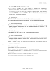
...;Under the manual test mode condition, operate SBS as the initial value.) Each time SBS is turned off SBS and MOS. Bulb release is possible. ©While "command 0" or "command 1" is "000h". FCA45001 - M 3 • Zoom 120 ED - Each time MOS is operated, the AF data is increased one by one . (After "5", "0" is reset.) When the commands 1-5 are set by one . (After the battery is completed...
...;Under the manual test mode condition, operate SBS as the initial value.) Each time SBS is turned off SBS and MOS. Bulb release is possible. ©While "command 0" or "command 1" is "000h". FCA45001 - M 3 • Zoom 120 ED - Each time MOS is operated, the AF data is increased one by one . (After "5", "0" is reset.) When the commands 1-5 are set by one . (After the battery is completed...
Repair Manual
Page 6
... MOS. The PAR set status is set in Procedure 2), operate the camera normally. ©The camera operates according to the set , the previous command is displayed as turning on ZDS at "2 minutes", the manual test mode is not canceled. ®If the camera back is opened while the bulb is opened, the bulb keeps open. ©Even if the test mode is displayed, operate MOS. Zoom 120 ED - Data setting is completed...
... MOS. The PAR set status is set in Procedure 2), operate the camera normally. ©The camera operates according to the set , the previous command is displayed as turning on ZDS at "2 minutes", the manual test mode is not canceled. ®If the camera back is opened while the bulb is opened, the bulb keeps open. ©Even if the test mode is displayed, operate MOS. Zoom 120 ED - Data setting is completed...
Repair Manual
Page 7
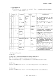
... and a bulb is displayed for 1 second since ZSW was turned off. NI 5 • Zoom 120 ED - Command No Command Display Deails of stop position is set. The value is changed with sexadecimal numbers. - BV data ISO value data Zoom position F/ P Each time S1 is displayed. The displayed metering operation data is displayed with the zoom switch. The ISO value read and the full size mode or panorama mode is...
... and a bulb is displayed for 1 second since ZSW was turned off. NI 5 • Zoom 120 ED - Command No Command Display Deails of stop position is set. The value is changed with sexadecimal numbers. - BV data ISO value data Zoom position F/ P Each time S1 is displayed. The displayed metering operation data is displayed with the zoom switch. The ISO value read and the full size mode or panorama mode is...
Repair Manual
Page 8
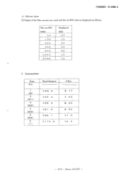
FCA45001 - A 4 ) ISO set value C)2 digits of the film counter are used and the set ISO value 50 1 0 0 2 0 0 4 0 0 8 0 0 1 6 0 0 3 2 0 0 Displayed data 05 10 20 40 8 0 1 6 32 5 . The set ISO value is displayed as follows. M6 • Zoom 120 ED - R. 3498. Zoom position Zone Re 1 (W) 2 (M1) 3 (M2) 4 (M3) 5 (M4) 6 (T) Focal distance f 39. 9 f 55. 3 f 68. 3 f 8 1. 6 f 96. 1 f 1 14. 0 FN o. 5. 77 7. 55 8. 83 9. 94 1 1. 0 12. 0 -
FCA45001 - A 4 ) ISO set value C)2 digits of the film counter are used and the set ISO value 50 1 0 0 2 0 0 4 0 0 8 0 0 1 6 0 0 3 2 0 0 Displayed data 05 10 20 40 8 0 1 6 32 5 . The set ISO value is displayed as follows. M6 • Zoom 120 ED - R. 3498. Zoom position Zone Re 1 (W) 2 (M1) 3 (M2) 4 (M3) 5 (M4) 6 (T) Focal distance f 39. 9 f 55. 3 f 68. 3 f 8 1. 6 f 96. 1 f 1 14. 0 FN o. 5. 77 7. 55 8. 83 9. 94 1 1. 0 12. 0 -
Repair Manual
Page 17
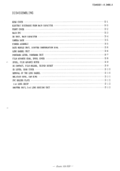
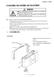
Zoom 120 ED - DISASSEMBLING REAR COVER ELECTRIC DISCHARGE FROM MAIN CAPACITOR FRONT COVER MAIN FPC SB UNIT, MAIN CAPACITOR CAMERA BACK FINDER ASSEMBLY DATE MODULE UNIT, DIOPTER COMPENSATION DIAL LENS BARREL UNIT PANORAMA LEVER, PANORAMA UNIT FILM ADVANCE GEAR, SPOOL COVER SPOOL, FILM ADVANCE MOTOR DX CONTACT, FILM HOLDER, TRIPOD SOCKET SB LEVER, GEAR COVER REMOVAL OF THE LENS BARREL HELICOID RING, CAM RING FPC HOLDER PLATE 1 st LENS GROUP SHUTTER UNIT, 3rd LENS HOUSING UNIT FCA45001--R.3498.A D1 D2 D2 D3 D4 D5 D5 D6 D6 D7 D8 D9 D9 D 10 D 10 D 1 1 D 1 2 D 1 2 D 1 2 -
Zoom 120 ED - DISASSEMBLING REAR COVER ELECTRIC DISCHARGE FROM MAIN CAPACITOR FRONT COVER MAIN FPC SB UNIT, MAIN CAPACITOR CAMERA BACK FINDER ASSEMBLY DATE MODULE UNIT, DIOPTER COMPENSATION DIAL LENS BARREL UNIT PANORAMA LEVER, PANORAMA UNIT FILM ADVANCE GEAR, SPOOL COVER SPOOL, FILM ADVANCE MOTOR DX CONTACT, FILM HOLDER, TRIPOD SOCKET SB LEVER, GEAR COVER REMOVAL OF THE LENS BARREL HELICOID RING, CAM RING FPC HOLDER PLATE 1 st LENS GROUP SHUTTER UNIT, 3rd LENS HOUSING UNIT FCA45001--R.3498.A D1 D2 D2 D3 D4 D5 D5 D6 D6 D7 D8 D9 D9 D 10 D 10 D 1 1 D 1 2 D 1 2 D 1 2 -
Repair Manual
Page 18
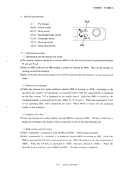
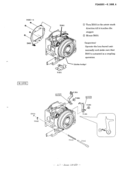
... static electricity from the main condenser according to the instruction in the repair manual after removing the rear cover Note : CDBe sure to take off the battery before disassembly. (DAt disassembly, make sure to memorize how to arrange the wires, how to fix the screws, and the types of used screws. ©Be sure to get yourself grounded because of this camera. DISASSEMBLING/ASSEMBLING/ADJUSTMENT FCA45001 -R. 3498.
... static electricity from the main condenser according to the instruction in the repair manual after removing the rear cover Note : CDBe sure to take off the battery before disassembly. (DAt disassembly, make sure to memorize how to arrange the wires, how to fix the screws, and the types of used screws. ©Be sure to get yourself grounded because of this camera. DISASSEMBLING/ASSEMBLING/ADJUSTMENT FCA45001 -R. 3498.
Repair Manual
Page 20
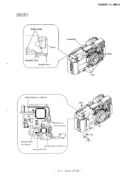
MAIN FPC Solde bridge Black 1 D' 51 0 /OJ Black(SB unit) Red(SB unit) Connector O # 404,7,1 Tape Pc Tape Black(Cathode on a ba_.t). tery) Orange(SB PCB) #817 O e 4 136 D 3 • Zoom 120 ED - FCA450-R0.13498A. e ye reduction lamp) 0 )O1 t1 O 00 Black(Cathode on a battery) Orange(Anode on a battery) 0 0 ° D 0 0 0 0 Blue (Re d -
MAIN FPC Solde bridge Black 1 D' 51 0 /OJ Black(SB unit) Red(SB unit) Connector O # 404,7,1 Tape Pc Tape Black(Cathode on a ba_.t). tery) Orange(SB PCB) #817 O e 4 136 D 3 • Zoom 120 ED - FCA450-R0.13498A. e ye reduction lamp) 0 )O1 t1 O 00 Black(Cathode on a battery) Orange(Anode on a battery) 0 0 ° D 0 0 0 0 Blue (Re d -
Repair Manual
Page 23
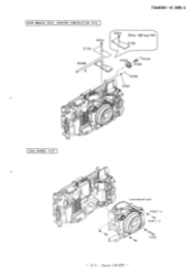
A DATE MODULE UNIT, DIOPTER COMPENSATION DIAL 814 11719 B1028 814 [Non-QD type )T11 #726 #51e8 v, tt.1 #520 519 '#\ c'N # 522 # 521 104.11111f0 4b4 1 LENS BARREL UNIT 0 0 0 0 0 0 a czo 0 Lens barrel unit IJ 0 0 663 x 4 827 x 3 g823 - D 6 • Zoom 120 ED FCA45001-R. 3498.
A DATE MODULE UNIT, DIOPTER COMPENSATION DIAL 814 11719 B1028 814 [Non-QD type )T11 #726 #51e8 v, tt.1 #520 519 '#\ c'N # 522 # 521 104.11111f0 4b4 1 LENS BARREL UNIT 0 0 0 0 0 0 a czo 0 Lens barrel unit IJ 0 0 663 x 4 827 x 3 g823 - D 6 • Zoom 120 ED FCA45001-R. 3498.
Repair Manual
Page 27
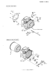
A # 801x 4 CD C1) B603 0 4 304 # 806 00 4644 0 O # 806 4 305 # 642 0 0 0 0 - 4 643 #661 (Solder bridge) # 641 REMOVAL OF THE LENS BARREL %.,e JT O 0 0 0 0 c'© # 655 #659 # 652 4 653 (`10 • 4 654 C 4 655 0 #813x2 B660 - D1 0 • Zoom 120 ED - SB LEVER, GEAR COVER FCA45001 -R. 3498.
A # 801x 4 CD C1) B603 0 4 304 # 806 00 4644 0 O # 806 4 305 # 642 0 0 0 0 - 4 643 #661 (Solder bridge) # 641 REMOVAL OF THE LENS BARREL %.,e JT O 0 0 0 0 c'© # 655 #659 # 652 4 653 (`10 • 4 654 C 4 655 0 #813x2 B660 - D1 0 • Zoom 120 ED - SB LEVER, GEAR COVER FCA45001 -R. 3498.
Repair Manual
Page 29
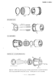
OD #647x 3 1011101■0210110MM #646x 3 1 st LENS GROUP #611 4634 SHUTTER UNIT, 3rd LENS HOUSING UNIT B61O // O 3rd lens housing unit #615X 3 Caution : In B61O, the 2nd lens group is already centered while it includes the shutter. D 1 2 • Zoom 120 ED - Don't disassemble B61O to keep the accuracy. FCA45001-R. 3498. A #626 #606 FPC HOLDER PLATE #8O5x 3 OD- All the parts are set as assembly. -
OD #647x 3 1011101■0210110MM #646x 3 1 st LENS GROUP #611 4634 SHUTTER UNIT, 3rd LENS HOUSING UNIT B61O // O 3rd lens housing unit #615X 3 Caution : In B61O, the 2nd lens group is already centered while it includes the shutter. D 1 2 • Zoom 120 ED - Don't disassemble B61O to keep the accuracy. FCA45001-R. 3498. A #626 #606 FPC HOLDER PLATE #8O5x 3 OD- All the parts are set as assembly. -
Repair Manual
Page 30
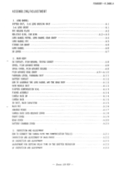
...(S) INSPECTION AND ADJUSTMENT OF BACK FOCUS AE INSPECTION AND ADJUSTMENT ADJUSTMENT FOR SETTING DELAY TIME IN THE SHUTTER MECHANISM AF INSPECTION AND ADJUSTMENT - Zoom 120 ED - MAIN FPC ARRANGE WIRES CAMERA BACK LOCK-RELEASE LEVER FRONT COVER REAR COVER BATTERY CHAMBER COVER 3. REAR BODY DX CONTACT, FILM HOLDER, TRIPOD SOCKET SPOOL, FILM ADVANCE MOTOR SPOOL COVER, FILM ADVANCE HOLDER FILM ADVANCE GEAR GROUP PANORAMA LEVER, PANORAMA UNIT BATTERY CONTACT HOW TO ASSEMBLE THE LENS BARREL AND THE REAR BODY DATE MODULE UNIT DIOPTER...
...(S) INSPECTION AND ADJUSTMENT OF BACK FOCUS AE INSPECTION AND ADJUSTMENT ADJUSTMENT FOR SETTING DELAY TIME IN THE SHUTTER MECHANISM AF INSPECTION AND ADJUSTMENT - Zoom 120 ED - MAIN FPC ARRANGE WIRES CAMERA BACK LOCK-RELEASE LEVER FRONT COVER REAR COVER BATTERY CHAMBER COVER 3. REAR BODY DX CONTACT, FILM HOLDER, TRIPOD SOCKET SPOOL, FILM ADVANCE MOTOR SPOOL COVER, FILM ADVANCE HOLDER FILM ADVANCE GEAR GROUP PANORAMA LEVER, PANORAMA UNIT BATTERY CONTACT HOW TO ASSEMBLE THE LENS BARREL AND THE REAR BODY DATE MODULE UNIT DIOPTER...
Repair Manual
Page 31
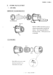
A ZCC C) 3rd lens housiT tilt #615x 3 Caution: In B610, the 2nd lens group is already centered while it as assembly. 1 st LENS GROUP #611 • • Move #634 in the right. #634 I / - Don't disassemble B610 to position it includes the shutter. A 1 • Zoom 120 ED - ASSEMBLING/ADJUSTMENT 1 . LENS BARREL SHUTTER UNIT, 3rd LENS HOUSING UNIT #612 B610 FCA45001-R. 3498. All the parts are set as illustrated in the arrow mark direction to keep the accuracy. 2.
A ZCC C) 3rd lens housiT tilt #615x 3 Caution: In B610, the 2nd lens group is already centered while it as assembly. 1 st LENS GROUP #611 • • Move #634 in the right. #634 I / - Don't disassemble B610 to position it includes the shutter. A 1 • Zoom 120 ED - ASSEMBLING/ADJUSTMENT 1 . LENS BARREL SHUTTER UNIT, 3rd LENS HOUSING UNIT #612 B610 FCA45001-R. 3498. All the parts are set as illustrated in the arrow mark direction to keep the accuracy. 2.
Repair Manual
Page 32
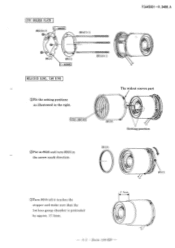
A2 • Zoom 120 ED - C- 8008B #647x 3 CD- // #637 #631 C- 8008B .astottima #646x 3 HELICOID RING, CAM RING OFit the setting positions as illustrated in the arrow mark direction. #626 #605 ©Turn #605 till it touches the stopper and make sure that the 1st lens group chamber is protruded by approx. 17.5mm. 17.5mm 1 - The widest convex part CFD- 005.5H #606 \ , Setting position ®Put in #626 and turn #605 in the right. FCA45001--R.3498.A FPC HOLDER PLATE #805x 3 CD-
A2 • Zoom 120 ED - C- 8008B #647x 3 CD- // #637 #631 C- 8008B .astottima #646x 3 HELICOID RING, CAM RING OFit the setting positions as illustrated in the arrow mark direction. #626 #605 ©Turn #605 till it touches the stopper and make sure that the 1st lens group chamber is protruded by approx. 17.5mm. 17.5mm 1 - The widest convex part CFD- 005.5H #606 \ , Setting position ®Put in #626 and turn #605 in the right. FCA45001--R.3498.A FPC HOLDER PLATE #805x 3 CD-

Repair Manual
Page 33
FCA45001--R.3498.A B606 CFD - 005.5H B603 The widest convex part a • • • • #602 CFD- 005.5H j (Setting position) ; Illommom • The widest groove • 0 Set the lens barrel to the TELE position. © Fit the setting positions as illustrated above. 0 Turn #602 in the arrow mark direction and fit the convex part of #606 into the groove of #602. #623 #622 P. C -8008B #616x 3 C - 8008B - I- A 3 • Zoom 120 ED -
FCA45001--R.3498.A B606 CFD - 005.5H B603 The widest convex part a • • • • #602 CFD- 005.5H j (Setting position) ; Illommom • The widest groove • 0 Set the lens barrel to the TELE position. © Fit the setting positions as illustrated above. 0 Turn #602 in the arrow mark direction and fit the convex part of #606 into the groove of #602. #623 #622 P. C -8008B #616x 3 C - 8008B - I- A 3 • Zoom 120 ED -
Repair Manual
Page 37
A # 801 x4 0 13503 00 B603 O 0 0 O # 661 0 Turn B503 in the arrow mark direction till it touches the stopper. 0 Mount B603. (Inspection) Operate the lens barrel unit manually and make sure that B503 is actuated in a coupling operation. (Solder bridge) SB LEVER G474C # 644 \ as, 642 0 O 0 0 O # 304 # 806 G474C # 806 # 305 643 ((to #641 O 0 A 7 • Zoom 120 ED - FCA45001 -R. 3498.
A # 801 x4 0 13503 00 B603 O 0 0 O # 661 0 Turn B503 in the arrow mark direction till it touches the stopper. 0 Mount B603. (Inspection) Operate the lens barrel unit manually and make sure that B503 is actuated in a coupling operation. (Solder bridge) SB LEVER G474C # 644 \ as, 642 0 O 0 0 O # 304 # 806 G474C # 806 # 305 643 ((to #641 O 0 A 7 • Zoom 120 ED - FCA45001 -R. 3498.
Repair Manual
Page 53
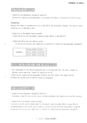
...'s accuracy. • Inspection in the manual inspection mode 1. FCA45001 -R. 3498. Check the EV by the adjustment software, the shutter tester should be sure to page M3,4,5) 2. Set up the inspection and adjustment software and then connect the camera with the shutter tester. A 2 3 • Zoom 120 ED - Confirm whether or not the AF step is instructed on the PC screen. Standard 0±0. 9 EV (LV 6) 07_4...
...'s accuracy. • Inspection in the manual inspection mode 1. FCA45001 -R. 3498. Check the EV by the adjustment software, the shutter tester should be sure to page M3,4,5) 2. Set up the inspection and adjustment software and then connect the camera with the shutter tester. A 2 3 • Zoom 120 ED - Confirm whether or not the AF step is instructed on the PC screen. Standard 0±0. 9 EV (LV 6) 07_4...
Repair Manual
Page 68
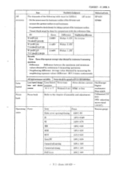
EV Error Difference Neighboring difference W:4 Visual check must be done by taking a picture of the luminance surface. FCA45001 - AE tester EF-511N • Set the camera near the luminance surface of the following table must be fulfilled. R.3498.A AE accuracy Item Standardofjudgment Method and tools The demands of the AE tester and EF8000 measure the aperture surface at each luminance. • It is permitted to check density by comparison with the reference film.
EV Error Difference Neighboring difference W:4 Visual check must be done by taking a picture of the luminance surface. FCA45001 - AE tester EF-511N • Set the camera near the luminance surface of the following table must be fulfilled. R.3498.A AE accuracy Item Standardofjudgment Method and tools The demands of the AE tester and EF8000 measure the aperture surface at each luminance. • It is permitted to check density by comparison with the reference film.
Repair Manual
Page 69
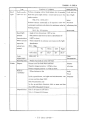
... more Stop watch Speed light • Angle of view for picture: -1EV or less division • The positive side must not have a disturbance of characteristics 0.3EV or more. (Wide end and • There should be no extreme unevenness in 2 times/sec under the Standard uncharged condition and obtain the minimum value by reflection plate flashing 3 times. R 3 • Zoom 120 ED - lEV...
... more Stop watch Speed light • Angle of view for picture: -1EV or less division • The positive side must not have a disturbance of characteristics 0.3EV or more. (Wide end and • There should be no extreme unevenness in 2 times/sec under the Standard uncharged condition and obtain the minimum value by reflection plate flashing 3 times. R 3 • Zoom 120 ED - lEV...


