
Hardware Installation Guide
Page 4
... switch, and USB console port. 4 Front Panels and LEDs The following : M4100-26G M4100-50G M4100-26-POE M4100-26G-POE M4100-50G-POE+ M4100-50-POE M4100-D10-POE M4100-D12G M4100-12GF M4100-D12G-POE+ M4100-24G-POE+ M4100-12G-POE+ This guide describes hardware installation and basic troubleshooting for each product, visit the NETGEAR website at http://www.netgear.com. They include powerful management features that you can be freestanding...
... switch, and USB console port. 4 Front Panels and LEDs The following : M4100-26G M4100-50G M4100-26-POE M4100-26G-POE M4100-50G-POE+ M4100-50-POE M4100-D10-POE M4100-D12G M4100-12GF M4100-D12G-POE+ M4100-24G-POE+ M4100-12G-POE+ This guide describes hardware installation and basic troubleshooting for each product, visit the NETGEAR website at http://www.netgear.com. They include powerful management features that you can be freestanding...

Hardware Installation Guide
Page 5
M4100-50-POE front panel POE ports RJ-45 ports SFP ports 5 M4100-50G front panel RJ-45 ports SFP SPD/Link/ACT mode: Green = Link at 1G Yellow = Link at 100M Blink = ACT SFP ports LEDs USB port Reset button Figure 3. NETGEAR Managed Switch LEDs USB port Reset button Figure 1. M4100-26G front panel RJ-45 ports SFP ports Combo Ports Power Fan RPS Reset USB RJ45 SPD/Link/ACT mode: Green = 1G Yellow = 10/100M Blink = ACT LEDs USB port Reset button Figure 2. M4100-26-POE front panel POE ports RJ-45 ports SFP ports LEDs USB port Reset button Figure 4.
M4100-50-POE front panel POE ports RJ-45 ports SFP ports 5 M4100-50G front panel RJ-45 ports SFP SPD/Link/ACT mode: Green = Link at 1G Yellow = Link at 100M Blink = ACT SFP ports LEDs USB port Reset button Figure 3. NETGEAR Managed Switch LEDs USB port Reset button Figure 1. M4100-26G front panel RJ-45 ports SFP ports Combo Ports Power Fan RPS Reset USB RJ45 SPD/Link/ACT mode: Green = 1G Yellow = 10/100M Blink = ACT LEDs USB port Reset button Figure 2. M4100-26-POE front panel POE ports RJ-45 ports SFP ports LEDs USB port Reset button Figure 4.

Hardware Installation Guide
Page 8
... device. Note: If combo port media change to fiber, the Ethernet LED changes to the switch. Off: RPS disconnected. NETGEAR Managed Switch Table 1. Blinking yellow: Indicates the PoE MAX LED was active in stopping power to PSE getting 802.3af specified power. Solid green: The fan is providing power...yellow: Power module is connected to that one of proper voltage (44 VDC-57 VDC for af, 50 VDC-57 VDC for M4100-26G, 50G, 26-POE, 26G-POE, 50G-POE+, and 50-POE Solid green: PD port 1 is present but RPS has failed. Note: Only for at 1000 Mbps. LED descriptions LED Power...
... device. Note: If combo port media change to fiber, the Ethernet LED changes to the switch. Off: RPS disconnected. NETGEAR Managed Switch Table 1. Blinking yellow: Indicates the PoE MAX LED was active in stopping power to PSE getting 802.3af specified power. Solid green: The fan is providing power...yellow: Power module is connected to that one of proper voltage (44 VDC-57 VDC for af, 50 VDC-57 VDC for M4100-26G, 50G, 26-POE, 26G-POE, 50G-POE+, and 50-POE Solid green: PD port 1 is present but RPS has failed. Note: Only for at 1000 Mbps. LED descriptions LED Power...

Hardware Installation Guide
Page 9
... yellow: A valid 100 Mbps SFP module link is connected and get 15.4 W power from PSE successfully. M4100-26G, 50G, 26-POE, 26G-POE, 50G-POE+, and 50-POE rear panels 9 Solid green: The PSE is established on the port at 1000 Mbps. Solid yellow: A valid...mini USB port (only for M4100-26G, 50G, 26-POE, 26G-POE, 50G-POE+, 50-POE, D12-PoE, and D12G), a redundant power supply connector (only for M4100-26G, 50G, 26-POE, 26G-POE, 50G-POE+, 50-POE, 12GF, 24G-POE+, and 12G-POE+), and a standard AC power receptacle for the supplied power cord. NETGEAR Managed Switch Table 1. LED ...
... yellow: A valid 100 Mbps SFP module link is connected and get 15.4 W power from PSE successfully. M4100-26G, 50G, 26-POE, 26G-POE, 50G-POE+, and 50-POE rear panels 9 Solid green: The PSE is established on the port at 1000 Mbps. Solid yellow: A valid...mini USB port (only for M4100-26G, 50G, 26-POE, 26G-POE, 50G-POE+, 50-POE, D12-PoE, and D12G), a redundant power supply connector (only for M4100-26G, 50G, 26-POE, 26G-POE, 50G-POE+, 50-POE, 12GF, 24G-POE+, and 12G-POE+), and a standard AC power receptacle for the supplied power cord. NETGEAR Managed Switch Table 1. LED ...

Hardware Installation Guide
Page 20
...-on self-test (POST). • If the switch passes the test, the LED turns green. The PSE device should light in the following checks: 1. NETGEAR Managed Switch Check the Installation Before you connect the power cord, select an AC outlet that is not controlled by a wall switch (which can turn... to Power and Check the LEDs The switch does not have an on the front panel of the switch. Note: The M4100-26G, 50G, 26-PoE, 26G-PoE, 50-PoE+, 50G-PoE, 12GF, 24G-POE+, 12G-POE+ can also obtain power from a PSE (power sourcing equipment) switch if AC power is to a grounded three-pronged AC ...
...-on self-test (POST). • If the switch passes the test, the LED turns green. The PSE device should light in the following checks: 1. NETGEAR Managed Switch Check the Installation Before you connect the power cord, select an AC outlet that is not controlled by a wall switch (which can turn... to Power and Check the LEDs The switch does not have an on the front panel of the switch. Note: The M4100-26G, 50G, 26-PoE, 26G-PoE, 50-PoE+, 50G-PoE, 12GF, 24G-POE+, 12G-POE+ can also obtain power from a PSE (power sourcing equipment) switch if AC power is to a grounded three-pronged AC ...

Hardware Installation Guide
Page 28
NETGEAR Managed Switch Table 6. Fast Ethernet switches physical specifications Fast Ethernet Switches M4100-26-POE (FSM7226P) M4100-50-POE (FSM7250P) M4100-D10-POE (FSM5210P) Interface (AutoUplink on all RJ-45 ports) 24 RJ-45 ports for 10/100 Mbps 48 RJ-45 ports for 10/100 Mbps 8 RJ-.../100/1000 Mbps 2 SFP ports for 100/1000 Mbps 2 SFP ports for 100/1000 Mbps 2 SFP ports for 100/1000 Mbps 24 PoE ports 48 IEEE802.3af PoE 8 IEEE802.3af PoE 1 USB type A connector ports ports RS-232 console port 1 USB type A connector 1 USB type A connector 1 USB mini B console RS-232 console port...
NETGEAR Managed Switch Table 6. Fast Ethernet switches physical specifications Fast Ethernet Switches M4100-26-POE (FSM7226P) M4100-50-POE (FSM7250P) M4100-D10-POE (FSM5210P) Interface (AutoUplink on all RJ-45 ports) 24 RJ-45 ports for 10/100 Mbps 48 RJ-45 ports for 10/100 Mbps 8 RJ-.../100/1000 Mbps 2 SFP ports for 100/1000 Mbps 2 SFP ports for 100/1000 Mbps 2 SFP ports for 100/1000 Mbps 24 PoE ports 48 IEEE802.3af PoE 8 IEEE802.3af PoE 1 USB type A connector ports ports RS-232 console port 1 USB type A connector 1 USB type A connector 1 USB mini B console RS-232 console port...
CLI Manual
Page 734
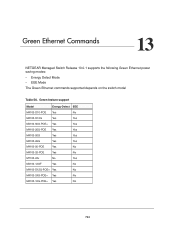
... Table 56. 13. Green feature support Model Energy-Detect EEE M4100-D10-POE Yes No M4100-D12G Yes Yes M4100-50G-POE+ Yes Yes M4100-26G-POE Yes Yes M4100-50G Yes Yes M4100-26G Yes Yes M4100-50-POE Yes No M4100-26-POE Yes No M7100-24x No Yes M4100-12GF Yes No M4100-D12G-POE+ Yes No M4100-24G-POE+ Yes No M4100-12G-POE+ Yes No 734
... Table 56. 13. Green feature support Model Energy-Detect EEE M4100-D10-POE Yes No M4100-D12G Yes Yes M4100-50G-POE+ Yes Yes M4100-26G-POE Yes Yes M4100-50G Yes Yes M4100-26G Yes Yes M4100-50-POE Yes No M4100-26-POE Yes No M7100-24x No Yes M4100-12GF Yes No M4100-D12G-POE+ Yes No M4100-24G-POE+ Yes No M4100-12G-POE+ Yes No 734


