GS7xxTS Hardware manual
Page 5
...Revision History ...xi Chapter 1 Introduction Overview ...1-13 Switch Features ...1-15 Stacking ...1-16 Package Contents ...1-17 Chapter 2 Installation Step 1: Preparing the Site 2-29 Step 2: Installing the Switch 2-30 Installing the Switch on a Flat Surface 2-30 Installing the Switch in a Rack 2-30 Step 3: Checking the ... AC Power 2-34 Step 8: Managing the Switch through a Web Browser or the PC Utility for Initial Configuration ...2-35 Chapter 3 Physical Description Front and Back Panel Configuration 3-19 GS724TS Front and Back Panels 3-19 GS748TS Front and Back Panels 3-20 v v1.0,...
...Revision History ...xi Chapter 1 Introduction Overview ...1-13 Switch Features ...1-15 Stacking ...1-16 Package Contents ...1-17 Chapter 2 Installation Step 1: Preparing the Site 2-29 Step 2: Installing the Switch 2-30 Installing the Switch on a Flat Surface 2-30 Installing the Switch in a Rack 2-30 Step 3: Checking the ... AC Power 2-34 Step 8: Managing the Switch through a Web Browser or the PC Utility for Initial Configuration ...2-35 Chapter 3 Physical Description Front and Back Panel Configuration 3-19 GS724TS Front and Back Panels 3-19 GS748TS Front and Back Panels 3-20 v v1.0,...
GS7xxTS Hardware manual
Page 10
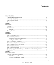
...ports. • GS748TS - To simplify installation, the switch is shipped ready for use a device as an introduction to six units for a maximunm of 192 10/100 ports or you can make high-speed connections using the Gigabit ports. You can stack together up to the GS700TS Smart Switch... and provides the following information: • Overview • Switch Features • Package Contents Overview This Installation Guide is for the following NETGEAR Smart Switches:...
...ports. • GS748TS - To simplify installation, the switch is shipped ready for use a device as an introduction to six units for a maximunm of 192 10/100 ports or you can make high-speed connections using the Gigabit ports. You can stack together up to the GS700TS Smart Switch... and provides the following information: • Overview • Switch Features • Package Contents Overview This Installation Guide is for the following NETGEAR Smart Switches:...
GS7xxTS Hardware manual
Page 13
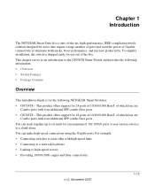
... address-learning function to six units per stack, or can operate as if all stack masters are a single unit. and half-duplex functions for all ports. • Auto Uplink™ on all 10/100/1000 Mbps ports. • Store-and-Forward transmission to... contains up to build the packet-forwarding information table. All stack masters are supported in a stack Introduction v1.0, November 2007 1-16 IEEE 802.3ab (1000Base-T) - GS700TS Hardware Installation Guide • The devices support full Netgear Smart Switch functionality and provide full compatibility with the following : •...
... address-learning function to six units per stack, or can operate as if all stack masters are a single unit. and half-duplex functions for all ports. • Auto Uplink™ on all 10/100/1000 Mbps ports. • Store-and-Forward transmission to... contains up to build the packet-forwarding information table. All stack masters are supported in a stack Introduction v1.0, November 2007 1-16 IEEE 802.3ab (1000Base-T) - GS700TS Hardware Installation Guide • The devices support full Netgear Smart Switch functionality and provide full compatibility with the following : •...
GS7xxTS Hardware manual
Page 14
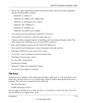
...as a single interface in the stack must be selected manually. Runs as the backup master. However, all units in which allows the applications running the same software version. A device can become a Master-Backup. • Slave - One of the NETGEAR Smart Switch 1-17 v1.0, November 2007 ...Introduction Package Contents Figure 1-2 shows the package contents of the Slave units will need to be running on the master unit to control and manage the stack. One of the slave units is designated as...
...as a single interface in the stack must be selected manually. Runs as the backup master. However, all units in which allows the applications running the same software version. A device can become a Master-Backup. • Slave - One of the NETGEAR Smart Switch 1-17 v1.0, November 2007 ...Introduction Package Contents Figure 1-2 shows the package contents of the Slave units will need to be running on the master unit to control and manage the stack. One of the slave units is designated as...
GS7xxTS Hardware manual
Page 20
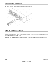
GS700TS Hardware Installation Guide 2. There are used for connecting the devices in a stack. Press firmly to ensure the module seats into the connector Figure 2-3 Step 6: Installing a Device The device can operate as part of the device are two stacking topologies supported by the device, the Ring topology or Chain topology. 2-33 v1.0, November 2007 Installation The HX stacking ports on the back of a stack.
GS700TS Hardware Installation Guide 2. There are used for connecting the devices in a stack. Press firmly to ensure the module seats into the connector Figure 2-3 Step 6: Installing a Device The device can operate as part of the device are two stacking topologies supported by the device, the Ring topology or Chain topology. 2-33 v1.0, November 2007 Installation The HX stacking ports on the back of a stack.
GS7xxTS Hardware manual
Page 21
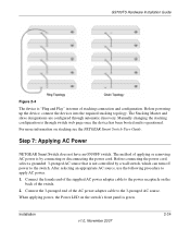
... power, the Power LED on stacking see the NETGEAR Smart Switch User Guide. Connect the 3-pronged end of stacking connection and configuration. For more information on the switch's front panel is operational. The Stacking Master and slave designations are configured through switch web page once the device has... been booted and is green. Step 7: Applying AC Power NETGEAR Smart Switch does not have an ON/OFF switch. Manually changing the stacking configuration is not controlled by connecting or disconnecting the power cord. Before connecting the power cord,...
... power, the Power LED on stacking see the NETGEAR Smart Switch User Guide. Connect the 3-pronged end of stacking connection and configuration. For more information on the switch's front panel is operational. The Stacking Master and slave designations are configured through switch web page once the device has... been booted and is green. Step 7: Applying AC Power NETGEAR Smart Switch does not have an ON/OFF switch. Manually changing the stacking configuration is not controlled by connecting or disconnecting the power cord. Before connecting the power cord,...
GS7xxTS Hardware manual
Page 24
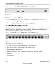
... 10Base-T, 100Base-T and 1000Base-T. • Four Gigabit Interface Converter (SFP) slots for full-duplex stacking linking. Figure 3-3 illustrates the NETGEAR GS748TS Smart Switch front panel: Figure 3-3 The front panel contains the following : • A 100-240VAC/50-60 Hz universal input, which is a 48-Port 10/100/1000 + 4-Port SFP Combo port smart stackable switch, with each RJ45 ports capable of sensing the line speed...
... 10Base-T, 100Base-T and 1000Base-T. • Four Gigabit Interface Converter (SFP) slots for full-duplex stacking linking. Figure 3-3 illustrates the NETGEAR GS748TS Smart Switch front panel: Figure 3-3 The front panel contains the following : • A 100-240VAC/50-60 Hz universal input, which is a 48-Port 10/100/1000 + 4-Port SFP Combo port smart stackable switch, with each RJ45 ports capable of sensing the line speed...
GS7xxTS Hardware manual
Page 25
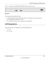
GS700TS Hardware Installation Guide Figure 3-2 illustrates the NETGEAR GS748TS Smart Switch back panel: Figure 3-4 The back panel contains the following LED types: • Port LEDs • System LEDs Physical Description v1.0, November 2007 3-21 LED Designations This section provides an explanation for the following : • A 100-240VAC/50-60 Hz universal input, which is a standard AC power receptacle for accommodating the supplied power cord. • Two 19 pin HX stacking ports for full-duplex stacking linking.
GS700TS Hardware Installation Guide Figure 3-2 illustrates the NETGEAR GS748TS Smart Switch back panel: Figure 3-4 The back panel contains the following LED types: • Port LEDs • System LEDs Physical Description v1.0, November 2007 3-21 LED Designations This section provides an explanation for the following : • A 100-240VAC/50-60 Hz universal input, which is a standard AC power receptacle for accommodating the supplied power cord. • Two 19 pin HX stacking ports for full-duplex stacking linking.
GS7xxTS Hardware manual
Page 26
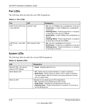
... established on the Up stacking port. 3-22 v1.0, November 2007 Physical Description One LED/Port 4-SFP Ports - Switch acts as a master unit in a stack of switches. • Solid Green - Switch acts as a slave member in stack mode. No 10/100Mbps link is occurring on the port. • Solid Green - No link is in a stack of switches. Table 3-2. The Stack Master LED is lit...
... established on the Up stacking port. 3-22 v1.0, November 2007 Physical Description One LED/Port 4-SFP Ports - Switch acts as a master unit in a stack of switches. • Solid Green - Switch acts as a slave member in stack mode. No 10/100Mbps link is occurring on the port. • Solid Green - No link is in a stack of switches. Table 3-2. The Stack Master LED is lit...
GS7xxTS Hardware manual
Page 27
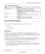
... transmission or reception is operating normally. • Solid Red - This technology allows attaching devices to the switch and is a straight-through or crossover cables. The fan is occurring on the Down stacking port. • Off - Indicates the Down stacking port link is disconnected. • Solid Green - Device Hardware Interfaces This section provides information for attaching...
... transmission or reception is operating normally. • Solid Red - This technology allows attaching devices to the switch and is a straight-through or crossover cables. The fan is occurring on the Down stacking port. • Off - Indicates the Down stacking port link is disconnected. • Solid Green - Device Hardware Interfaces This section provides information for attaching...
GS7xxTS Hardware manual
Page 32
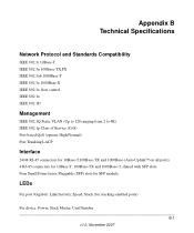
LEDs Per port (Gigabit): Link/Activity, Speed, Stack (for 10Base-T ,100Base-TX and 1000Base-T, shared with SFP slots. Appendix B Technical Specifications Network Protocol and Standards Compatibility IEEE 802.3i 10Base-T IEEE 802.3u ... 2 to 4K) IEEE 802.1p Class of Service (CoS) Port-based QoS (options High/Normal) Port Trunking LACP Interface 24/48 RJ-45 connectors for 10Base-T,100Base-TX and 1000Base-(Auto Uplink™ on all ports). 4 RJ-45 connectors for stacking-enabled ports) Per device: Power, Stack Master, Unit Number B-1 v1.0, November 2007 Four Small Form-factor...
LEDs Per port (Gigabit): Link/Activity, Speed, Stack (for 10Base-T ,100Base-TX and 1000Base-T, shared with SFP slots. Appendix B Technical Specifications Network Protocol and Standards Compatibility IEEE 802.3i 10Base-T IEEE 802.3u ... 2 to 4K) IEEE 802.1p Class of Service (CoS) Port-based QoS (options High/Normal) Port Trunking LACP Interface 24/48 RJ-45 connectors for 10Base-T,100Base-TX and 1000Base-(Auto Uplink™ on all ports). 4 RJ-45 connectors for stacking-enabled ports) Per device: Power, Stack Master, Unit Number B-1 v1.0, November 2007 Four Small Form-factor...
GS7xxTS Hardware manual
Page 33
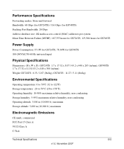
... Gbps (for GS724TS) / 116 Gbps (for GS748TS) Stacking Port Bandwidth: 20 Gbps Address database size: 4K media access control (MAC) addresses per system Mean Time Between Failure (MTBF): 167,355 hours for GS724TS, 125,566 hours for GS748TS Power Supply Power Consumption: 35.1W for GS724TS,... 78.36W for GS748TS 100-240VAC/50-60 Hz universal input Physical Specifications Dimensions: (H x W x D): GS724TS: 1.7 x 17.32 x 8....
... Gbps (for GS724TS) / 116 Gbps (for GS748TS) Stacking Port Bandwidth: 20 Gbps Address database size: 4K media access control (MAC) addresses per system Mean Time Between Failure (MTBF): 167,355 hours for GS724TS, 125,566 hours for GS748TS Power Supply Power Consumption: 35.1W for GS724TS,... 78.36W for GS748TS 100-240VAC/50-60 Hz universal input Physical Specifications Dimensions: (H x W x D): GS724TS: 1.7 x 17.32 x 8....
GS7xxTS User Manual
Page 6
GS700TS Smart Switch Software Administration Manual Chapter 3 Managing System Settings Using the System Settings Utility 3-1 Management ...3-1 System Information 3-1 IP Configuration ...3-4 Time ...3-5 Device View ...3-8 Stacking ...3-8 Operation Modes ...3-9 Understanding Stack Topology 3-9 Stacking Ports ...3-10 Stacking Members and Unit No 3-10 Removing and Replacing Stacking Members 3-11 Inserting a Stacking Member 3-12 Exchanging Stacking Members 3-12 Switching the Stacking Master 3-13 Stack Configuration and Management 3-13 SNMP ...3-17...
GS700TS Smart Switch Software Administration Manual Chapter 3 Managing System Settings Using the System Settings Utility 3-1 Management ...3-1 System Information 3-1 IP Configuration ...3-4 Time ...3-5 Device View ...3-8 Stacking ...3-8 Operation Modes ...3-9 Understanding Stack Topology 3-9 Stacking Ports ...3-10 Stacking Members and Unit No 3-10 Removing and Replacing Stacking Members 3-11 Inserting a Stacking Member 3-12 Exchanging Stacking Members 3-12 Switching the Stacking Master 3-13 Stack Configuration and Management 3-13 SNMP ...3-17...
GS7xxTS User Manual
Page 23
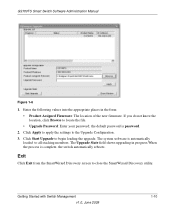
... of the new firmware. If you do not know the location, click Browse to the Upgrade Configuration. 3. Getting Started with Switch Management v1.0, June 2009 1-10 Click Apply to apply the settings to locate the file. • Upgrade Password: Enter your...the SmartWizard Discovery screen to begin loading the upgrade. The system software is complete, the switch automatically reboots. Click Start Upgrade to close the SmartWizard Discovery utility. GS700TS Smart Switch Software Administration Manual Figure 1-6 1. the default password is password. 2. Enter the following values...
... of the new firmware. If you do not know the location, click Browse to the Upgrade Configuration. 3. Getting Started with Switch Management v1.0, June 2009 1-10 Click Apply to apply the settings to locate the file. • Upgrade Password: Enter your...the SmartWizard Discovery screen to begin loading the upgrade. The system software is complete, the switch automatically reboots. Click Start Upgrade to close the SmartWizard Discovery utility. GS700TS Smart Switch Software Administration Manual Figure 1-6 1. the default password is password. 2. Enter the following values...

GS7xxTS User Manual
Page 32
... the Web Browser Interface v1.0, June 2009 Figure 2-12 3. This sets all the port boxes f for Unit 1, marking the ports as Tagged. GS700TS Smart Switch Software Administration Manual Quick Boxes Quick Boxes provide users with flexibility in configuring VLANs for ...this field. To mark or unmark all Tagged. The following example displays quick box basic usage options. Click on the left of the gold button. Clicking on a stacking...
... the Web Browser Interface v1.0, June 2009 Figure 2-12 3. This sets all the port boxes f for Unit 1, marking the ports as Tagged. GS700TS Smart Switch Software Administration Manual Quick Boxes Quick Boxes provide users with flexibility in configuring VLANs for ...this field. To mark or unmark all Tagged. The following example displays quick box basic usage options. Click on the left of the gold button. Clicking on a stacking...
GS7xxTS User Manual
Page 33
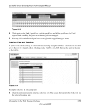
... may click on individual port boxes to the Web Browser Interface v1.0, June 2009 2-10 You may be selected from a table by using the interface selection row, located above the row of all ports in the selected stacking unit. or LAGS displays the ports in the unit or ...the LAGs: Figure 2-14 To display all ports in a stacking unit: 1. Click the unit number in the interface selection row. Click again on the Unit No. GS700TS Smart Switch Software Administration Manual Figure 2-...
... may click on individual port boxes to the Web Browser Interface v1.0, June 2009 2-10 You may be selected from a table by using the interface selection row, located above the row of all ports in the selected stacking unit. or LAGS displays the ports in the unit or ...the LAGs: Figure 2-14 To display all ports in a stacking unit: 1. Click the unit number in the interface selection row. Click again on the Unit No. GS700TS Smart Switch Software Administration Manual Figure 2-...
GS7xxTS User Manual
Page 34
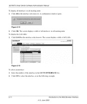
... selection row. Click GO to the Web Browser Interface v1.0, June 2009 The screen displays a table of the interface in all stacking units: 1. Enter the number of all stacking units. GS700TS Smart Switch Software Administration Manual To display all interfaces in the GO TO INTERFACE box. 2. Click All in all LAGs. A confirmation window opens...
... selection row. Click GO to the Web Browser Interface v1.0, June 2009 The screen displays a table of the interface in all stacking units: 1. Enter the number of all stacking units. GS700TS Smart Switch Software Administration Manual To display all interfaces in the GO TO INTERFACE box. 2. Click All in all LAGs. A confirmation window opens...
GS7xxTS User Manual
Page 36
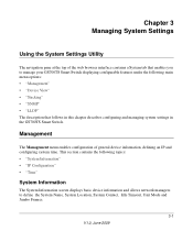
...browser interface contains a System tab that follows in this chapter describes configuring and managing system settings in the GS700TS Smart Switch. Chapter 3 Managing System Settings Using the System Settings Utility The navigation pane at the top of general device ... contains the following main menu options: • "Management" • "Device View" • "Stacking" • "SNMP" • "LLDP" The description that enables you to manage your GS700TS Smart Switch displaying configurable features under the following topics: • "System Information" • "IP Configuration" &#...
...browser interface contains a System tab that follows in this chapter describes configuring and managing system settings in the GS700TS Smart Switch. Chapter 3 Managing System Settings Using the System Settings Utility The navigation pane at the top of general device ... contains the following main menu options: • "Management" • "Device View" • "Stacking" • "SNMP" • "LLDP" The description that enables you to manage your GS700TS Smart Switch displaying configurable features under the following topics: • "System Information" • "IP Configuration" &#...
GS7xxTS User Manual
Page 38
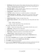
...are 1-6. • Model Name - Disable - Disables Jumbo Frames. The Versions Table displays the following fields: • Unit No. - Displays the stacking member's current number. Possible values are : - Click APPLY to enable or disable Jumbo Frames After Reset. 5. Select the Jumbo Frame status. Displays the.... 3-3 V1.0, June 2009 Select whether to update the system settings. 6. If the displayed Unit Mode needs to the value indicated by Stack or Standalone after resetting the device. • Jumbo Frames Status - If the device is displayed. • Serial Number - Toggle the...
...are 1-6. • Model Name - Disable - Disables Jumbo Frames. The Versions Table displays the following fields: • Unit No. - Displays the stacking member's current number. Possible values are : - Click APPLY to enable or disable Jumbo Frames After Reset. 5. Select the Jumbo Frame status. Displays the.... 3-3 V1.0, June 2009 Select whether to update the system settings. 6. If the displayed Unit Mode needs to the value indicated by Stack or Standalone after resetting the device. • Jumbo Frames Status - If the device is displayed. • Serial Number - Toggle the...
GS7xxTS User Manual
Page 43
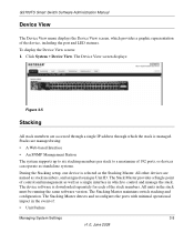
... Stacking Master maintains switch stacking and configuration. GS700TS Smart Switch Software Administration Manual Device View The Device View menu displays the Device View screen, which provides a graphic representation of the stack members. Click System > Device View. The device software is selected as stack members, and assigned a unique Unit ID. All units in which to a maximum of 192 ports...
... Stacking Master maintains switch stacking and configuration. GS700TS Smart Switch Software Administration Manual Device View The Device View menu displays the Device View screen, which provides a graphic representation of the stack members. Click System > Device View. The device software is selected as stack members, and assigned a unique Unit ID. All units in which to a maximum of 192 ports...