
GS7xxTS Hardware manual
Page 5
...Guide Conventions, Formats and Scope ix How to Use This Manual x How to Print this Manual ...x Revision History ...xi Chapter 1 Introduction Overview ...1-13 Switch Features ...1-15 Stacking ...1-16 Package Contents ...1-17 Chapter 2 Installation Step 1: Preparing the Site 2-29 Step 2: Installing the Switch 2-30 Installing the Switch on a Flat Surface 2-30 Installing the Switch... the Switch through a Web Browser or the PC Utility for Initial Configuration ...2-35 Chapter 3 Physical Description Front and Back Panel Configuration 3-19 GS724TS Front and Back Panels 3-19 GS748TS Front and...
...Guide Conventions, Formats and Scope ix How to Use This Manual x How to Print this Manual ...x Revision History ...xi Chapter 1 Introduction Overview ...1-13 Switch Features ...1-15 Stacking ...1-16 Package Contents ...1-17 Chapter 2 Installation Step 1: Preparing the Site 2-29 Step 2: Installing the Switch 2-30 Installing the Switch on a Flat Surface 2-30 Installing the Switch... the Switch through a Web Browser or the PC Utility for Initial Configuration ...2-35 Chapter 3 Physical Description Front and Back Panel Configuration 3-19 GS724TS Front and Back Panels 3-19 GS748TS Front and...
GS7xxTS Hardware manual
Page 10
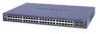
... additional SFP combo fiber ports. This product offers support for 48 ports of 10/100/1000 BaseT of 192 10/100 ports or you can use out of Gigabit connectivity to the GS700TS Smart Switch and provides the following information: • Overview • Switch Features • Package Contents Overview This Installation Guide is for the following NETGEAR Smart Switches: • GS724TS - This...
... additional SFP combo fiber ports. This product offers support for 48 ports of 10/100/1000 BaseT of 192 10/100 ports or you can use out of Gigabit connectivity to the GS700TS Smart Switch and provides the following information: • Overview • Switch Features • Package Contents Overview This Installation Guide is for the following NETGEAR Smart Switches: • GS724TS - This...
GS7xxTS Hardware manual
Page 13
... 802.3x (Full-duplex flow control) - All stack masters are supported in a stack Introduction v1.0, November 2007 1-16 Up to 192 10/100/1000 ports are accessed through a single IP address through a single point as stand-alone units. GS700TS Hardware Installation Guide • The devices support full Netgear Smart Switch functionality and provide full compatibility with the...
... 802.3x (Full-duplex flow control) - All stack masters are supported in a stack Introduction v1.0, November 2007 1-16 Up to 192 10/100/1000 ports are accessed through a single IP address through a single point as stand-alone units. GS700TS Hardware Installation Guide • The devices support full Netgear Smart Switch functionality and provide full compatibility with the...
GS7xxTS Hardware manual
Page 14
... 2. The backup master acts as slave stack members, and assigned a unique Unit ID. Switch software is downloaded separately for the configuration. • Master-Backup - Package Contents Figure 1-2 shows the package contents of the NETGEAR Smart Switch 1-17 v1.0, November 2007 Introduction GS700TS Hardware Installation Guide During the Stacking setup, the switches will auto-select one of the following...
... 2. The backup master acts as slave stack members, and assigned a unique Unit ID. Switch software is downloaded separately for the configuration. • Master-Backup - Package Contents Figure 1-2 shows the package contents of the NETGEAR Smart Switch 1-17 v1.0, November 2007 Introduction GS700TS Hardware Installation Guide During the Stacking setup, the switches will auto-select one of the following...
GS7xxTS Hardware manual
Page 20
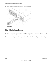
The HX stacking ports on the back of a stack. There are used for connecting the devices in a stack. Press firmly to ensure the module seats into the connector Figure 2-3 Step 6: Installing a Device The device can operate as part of the device are two stacking topologies supported by the device, the Ring topology or Chain topology. 2-33 v1.0, November 2007 Installation GS700TS Hardware Installation Guide 2.
The HX stacking ports on the back of a stack. There are used for connecting the devices in a stack. Press firmly to ensure the module seats into the connector Figure 2-3 Step 6: Installing a Device The device can operate as part of the device are two stacking topologies supported by the device, the Ring topology or Chain topology. 2-33 v1.0, November 2007 Installation GS700TS Hardware Installation Guide 2.
GS7xxTS Hardware manual
Page 21
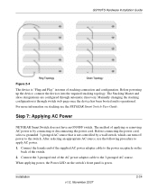
... and is green. After selecting an appropriate AC source, use the following procedure to apply AC power. 1. When applying power, the Power LED on stacking see the NETGEAR Smart Switch User Guide. Installation v1.0, November 2007 2-34 Before connecting the power cord, select a grounded 3-pronged AC source that is not controlled by connecting or disconnecting...
... and is green. After selecting an appropriate AC source, use the following procedure to apply AC power. 1. When applying power, the Power LED on stacking see the NETGEAR Smart Switch User Guide. Installation v1.0, November 2007 2-34 Before connecting the power cord, select a grounded 3-pronged AC source that is not controlled by connecting or disconnecting...
GS7xxTS Hardware manual
Page 24
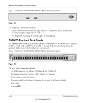
..., which is a 48-Port 10/100/1000 + 4-Port SFP Combo port smart stackable switch, with each RJ45 ports capable of sensing the line speed and negotiating the operation duplex mode with the link partner automatically. GS748TS Front and Back Panels The NETGEAR GS748TS Smart Switch is a standard AC power receptacle for accommodating the supplied power cord. • Two 19 pin HX stacking ports for SFP...
..., which is a 48-Port 10/100/1000 + 4-Port SFP Combo port smart stackable switch, with each RJ45 ports capable of sensing the line speed and negotiating the operation duplex mode with the link partner automatically. GS748TS Front and Back Panels The NETGEAR GS748TS Smart Switch is a standard AC power receptacle for accommodating the supplied power cord. • Two 19 pin HX stacking ports for SFP...
GS7xxTS Hardware manual
Page 25
GS700TS Hardware Installation Guide Figure 3-2 illustrates the NETGEAR GS748TS Smart Switch back panel: Figure 3-4 The back panel contains the following LED types: • Port LEDs • System LEDs Physical Description v1.0, November 2007 3-21 LED Designations This section provides an explanation for the following : • A 100-240VAC/50-60 Hz universal input, which is a standard AC power receptacle for accommodating the supplied power cord. • Two 19 pin HX stacking ports for full-duplex stacking linking.
GS700TS Hardware Installation Guide Figure 3-2 illustrates the NETGEAR GS748TS Smart Switch back panel: Figure 3-4 The back panel contains the following LED types: • Port LEDs • System LEDs Physical Description v1.0, November 2007 3-21 LED Designations This section provides an explanation for the following : • A 100-240VAC/50-60 Hz universal input, which is a standard AC power receptacle for accommodating the supplied power cord. • Two 19 pin HX stacking ports for full-duplex stacking linking.
GS7xxTS Hardware manual
Page 26
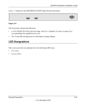
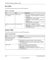
... is occurring on the Up stacking port. 3-22 v1.0, November 2007 Physical Description Port LEDs Port LED 24/48-10/100/1000 Ports Link/ACT LED - Packet transmission or reception is occurring on the port at 100Mbps. • Solid Yellow - No link is established on the port. • Solid Green - GS700TS Hardware Installation Guide Port LEDs The following table describes...
... is occurring on the Up stacking port. 3-22 v1.0, November 2007 Physical Description Port LEDs Port LED 24/48-10/100/1000 Ports Link/ACT LED - Packet transmission or reception is occurring on the port at 100Mbps. • Solid Yellow - No link is established on the port. • Solid Green - GS700TS Hardware Installation Guide Port LEDs The following table describes...
GS7xxTS Hardware manual
Page 27
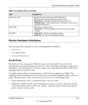
... (such as when connecting the port to the switch and is not operating normally. To simplify the procedure for the following hardware interfaces: • RJ-45 Ports • SFP GBIC Module • Factory Defaults Button RJ-45 Ports RJ-45ports are auto-sensing ports. GS700TS Hardware Installation Guide Table 3-2. Indicates the Down stacking port link is operating normally...
... (such as when connecting the port to the switch and is not operating normally. To simplify the procedure for the following hardware interfaces: • RJ-45 Ports • SFP GBIC Module • Factory Defaults Button RJ-45 Ports RJ-45ports are auto-sensing ports. GS700TS Hardware Installation Guide Table 3-2. Indicates the Down stacking port link is operating normally...