GS7xxTS Hardware manual
Page 6
... Hardware Interfaces 3-23 RJ-45 Ports ...3-23 SFP GBIC Module 3-24 Factory Defaults Button 3-24 Appendix A Troubleshooting Troubleshooting Chart A-1 Additional Troubleshooting Suggestions A-2 Network Adapter Cards A-2 Configuration ...A-2 Switch Integrity ...A-2 Auto-negotiation ...A-3 Appendix B Technical Specifications Network Protocol and Standards Compatibility B-1 Management ...B-1 Interface ...B-1 LEDs ...B-1 Performance Specifications B-2 Power Supply ...B-2 Physical Specifications B-2 Environmental Specifications B-2 Electromagnetic Emissions B-2 Electromagnetic Immunity...
... Hardware Interfaces 3-23 RJ-45 Ports ...3-23 SFP GBIC Module 3-24 Factory Defaults Button 3-24 Appendix A Troubleshooting Troubleshooting Chart A-1 Additional Troubleshooting Suggestions A-2 Network Adapter Cards A-2 Configuration ...A-2 Switch Integrity ...A-2 Auto-negotiation ...A-3 Appendix B Technical Specifications Network Protocol and Standards Compatibility B-1 Management ...B-1 Interface ...B-1 LEDs ...B-1 Performance Specifications B-2 Power Supply ...B-2 Physical Specifications B-2 Environmental Specifications B-2 Electromagnetic Emissions B-2 Electromagnetic Immunity...
GS7xxTS Hardware manual
Page 8
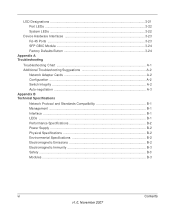
web site at the top right of any page. - How to Use This Manual The HTML version of This Chapter link at http://kbserver.netgear.com/main.asp. Click the PDF of this manual you can select one page • The button displays the table of contents or ... page in the HTML version of the chapter you want to where the topic is written for the GS700TS according to these specifications: Product Version Manual Publication Date GS700TS Smart Switch November 2007 Note: Product updates are available on the browser toolbar to your requirements. • Printing a Page in the HTML View ...
web site at the top right of any page. - How to Use This Manual The HTML version of This Chapter link at http://kbserver.netgear.com/main.asp. Click the PDF of this manual you can select one page • The button displays the table of contents or ... page in the HTML version of the chapter you want to where the topic is written for the GS700TS according to these specifications: Product Version Manual Publication Date GS700TS Smart Switch November 2007 Note: Product updates are available on the browser toolbar to your requirements. • Printing a Page in the HTML View ...

GS7xxTS Hardware manual
Page 17
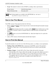
...Figure 2-1). Do not restrict airflow by a wall switch, which can be installed on the sides of the switch. 2. Be sure there is installed. • Operating conditions - Step 2: Installing the Switch The NETGEAR Smart Switch can accidentally turn off power to secure each ..., warm air exhausts, hot-air vents, and heaters. • Operating humidity - Keep the switch at least 2 inches (5.08 centimeters) free on a Flat Surface The switch ships with switch. 1. Power specifications for cooling. Keep the switch away from nearest source of the installation location.
...Figure 2-1). Do not restrict airflow by a wall switch, which can be installed on the sides of the switch. 2. Be sure there is installed. • Operating conditions - Step 2: Installing the Switch The NETGEAR Smart Switch can accidentally turn off power to secure each ..., warm air exhausts, hot-air vents, and heaters. • Operating humidity - Keep the switch at least 2 inches (5.08 centimeters) free on a Flat Surface The switch ships with switch. 1. Power specifications for cooling. Keep the switch away from nearest source of the installation location.
GS7xxTS Hardware manual
Page 19
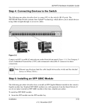
Note: Ethernet specifications limit the cable length between the switch and the attached device to install an SFP GBIC module at this time, skip this procedure. Standard SFP GBIC modules are sold separately from the Smart Switch. Insert the SFP ...Gigabit Ethernet module in the switch's Gigabit module bay. Step 5: Installing an SFP GBIC Module The following procedure describes how to connect PCs to the switch's RJ-45 ports. To install an SFP GBIC module: 1. Figure 2-2 Connect each PC to attach devices using either straight-through or crossover cables. The NETGEAR Smart Switch...
Note: Ethernet specifications limit the cable length between the switch and the attached device to install an SFP GBIC module at this time, skip this procedure. Standard SFP GBIC modules are sold separately from the Smart Switch. Insert the SFP ...Gigabit Ethernet module in the switch's Gigabit module bay. Step 5: Installing an SFP GBIC Module The following procedure describes how to connect PCs to the switch's RJ-45 ports. To install an SFP GBIC module: 1. Figure 2-2 Connect each PC to attach devices using either straight-through or crossover cables. The NETGEAR Smart Switch...

GS7xxTS Hardware manual
Page 29
... the NETGEAR Smart Switch. No power is set to autonegotiate. Check for the switch at both the switch and the connecting device. A-1 v1.0, November 2007 Check the power cord connections for a defective adapter card, cable, or port by testing them in an alternate environment where all cables are used correctly and comply with the Ethernet specifications. Make...
... the NETGEAR Smart Switch. No power is set to autonegotiate. Check for the switch at both the switch and the connecting device. A-1 v1.0, November 2007 Check the power cord connections for a defective adapter card, cable, or port by testing them in an alternate environment where all cables are used correctly and comply with the Ethernet specifications. Make...
GS7xxTS Hardware manual
Page 32
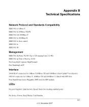
Four Small Form-factor Pluggable (SFP) slots for stacking-enabled ports) Per device: Power, Stack Master, Unit Number B-1 v1.0, November 2007 LEDs Per port (Gigabit): Link/Activity, Speed, Stack (for SFP module. Appendix B Technical Specifications Network Protocol and Standards Compatibility IEEE 802.3i 10Base-T IEEE 802....from 2 to 4K) IEEE 802.1p Class of Service (CoS) Port-based QoS (options High/Normal) Port Trunking LACP Interface 24/48 RJ-45 connectors for 10Base-T,100Base-TX and 1000Base-(Auto Uplink™ on all ports). 4 RJ-45 connectors for 10Base-T ,100Base-TX and 1000Base-T, ...
Four Small Form-factor Pluggable (SFP) slots for stacking-enabled ports) Per device: Power, Stack Master, Unit Number B-1 v1.0, November 2007 LEDs Per port (Gigabit): Link/Activity, Speed, Stack (for SFP module. Appendix B Technical Specifications Network Protocol and Standards Compatibility IEEE 802.3i 10Base-T IEEE 802....from 2 to 4K) IEEE 802.1p Class of Service (CoS) Port-based QoS (options High/Normal) Port Trunking LACP Interface 24/48 RJ-45 connectors for 10Base-T,100Base-TX and 1000Base-(Auto Uplink™ on all ports). 4 RJ-45 connectors for 10Base-T ,100Base-TX and 1000Base-T, ...
GS7xxTS Hardware manual
Page 33
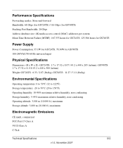
... (for GS748TS) Stacking Port Bandwidth: 20 Gbps Address database size: 4K media access control (MAC) addresses per system Mean Time Between Failure (MTBF): 167,355 hours for GS724TS, 125,566 hours for GS748TS Power Supply Power Consumption: 35.1W for GS724TS, 78.36W for GS748TS 100-240VAC/50-60 Hz universal input Physical Specifications Dimensions...
... (for GS748TS) Stacking Port Bandwidth: 20 Gbps Address database size: 4K media access control (MAC) addresses per system Mean Time Between Failure (MTBF): 167,355 hours for GS724TS, 125,566 hours for GS748TS Power Supply Power Consumption: 35.1W for GS724TS, 78.36W for GS748TS 100-240VAC/50-60 Hz universal input Physical Specifications Dimensions...

GS7xxTS Hardware manual
Page 34
Electromagnetic Immunity EN 55022 (CISPR 22), Class A Safety CE mark, commercial UL listed (UL 1950) / CUL IEC950 / EN60950 Modules AGM731F 1000Base-SX SFP GBIC for multimode fiber AGM732F 1000Base-LX SFP GBIC for single mode fiber AGM733 1000Base-LZ GBIC for long haul single mode fiber B-3 Technical Specifications v1.0, November 2007
Electromagnetic Immunity EN 55022 (CISPR 22), Class A Safety CE mark, commercial UL listed (UL 1950) / CUL IEC950 / EN60950 Modules AGM731F 1000Base-SX SFP GBIC for multimode fiber AGM732F 1000Base-LX SFP GBIC for single mode fiber AGM733 1000Base-LZ GBIC for long haul single mode fiber B-3 Technical Specifications v1.0, November 2007
GS7xxTS User Manual
Page 11
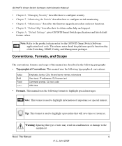
... help and support. • Chapter A, "Default Settings" gives GS700TS Smart Switch specifications and lists default feature values. About This Manual xi v1.0, June 2009 GS700TS Smart Switch Software Administration Manual • Chapter 6, "Managing Security" describes how to configure security. • Chapter 7, "Monitoring the Switch" describes how to configure switch monitoring. • Chapter 8, "Maintenance" describes the firmware upgrade...
... help and support. • Chapter A, "Default Settings" gives GS700TS Smart Switch specifications and lists default feature values. About This Manual xi v1.0, June 2009 GS700TS Smart Switch Software Administration Manual • Chapter 6, "Managing Security" describes how to configure security. • Chapter 7, "Monitoring the Switch" describes how to configure switch monitoring. • Chapter 8, "Maintenance" describes the firmware upgrade...

GS7xxTS User Manual
Page 12
... in the table of the full manual and individual chapters. Double-click on the NETGEAR, Inc. Failure to access the full NETGEAR, Inc. This manual is written for the GS700TS Smart Switch according to PDF versions of contents or index to navigate directly to where the topic...;A button that displays the table of this manual includes the following: • Buttons and at http://www.netgear.com/support. for the product model. • Links to these specifications: Product Version Manual Publication Date GS700TS Gigabit Stackable Smart Switch June 2009 . website at a time.
... in the table of the full manual and individual chapters. Double-click on the NETGEAR, Inc. Failure to access the full NETGEAR, Inc. This manual is written for the GS700TS Smart Switch according to PDF versions of contents or index to navigate directly to where the topic...;A button that displays the table of this manual includes the following: • Buttons and at http://www.netgear.com/support. for the product model. • Links to these specifications: Product Version Manual Publication Date GS700TS Gigabit Stackable Smart Switch June 2009 . website at a time.

GS7xxTS User Manual
Page 14
... "System Requirements" • "Switch Management Interface" • "Network with Switch Management This section provides an overview of switch management, including the methods you through...Smart Switch Software Administration Manual Chapter 1 Getting Started with a DHCP Server" • "Network without DHCP server as appropriate - It also leads you can choose to run the applications described in this manual: • Network facilities: - IBM-type PC with CD drive: RAM size and disk specification are required to start managing your NETGEAR GS700TS Gigabit Stackable Smart Switch...
... "System Requirements" • "Switch Management Interface" • "Network with Switch Management This section provides an overview of switch management, including the methods you through...Smart Switch Software Administration Manual Chapter 1 Getting Started with a DHCP Server" • "Network without DHCP server as appropriate - It also leads you can choose to run the applications described in this manual: • Network facilities: - IBM-type PC with CD drive: RAM size and disk specification are required to start managing your NETGEAR GS700TS Gigabit Stackable Smart Switch...
GS7xxTS User Manual
Page 26
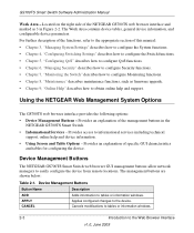
... in Figure 2-2. Device Management Buttons The NETGEAR GS700TS Smart Switch web browser GUI management buttons allow network managers to the device. Using the NETGEAR Web Management System Options The GS700TS web ...Smart Switch Software Administration Manual Work Area - For further description of the functions, refer to obtain online help and device information. • Using Screen and Table Options - Device Management Buttons Button Name Description ADD APPLY CANCEL Adds information to the Web Browser Interface v1.0, June 2009 Located on the right side of specific...
... in Figure 2-2. Device Management Buttons The NETGEAR GS700TS Smart Switch web browser GUI management buttons allow network managers to the device. Using the NETGEAR Web Management System Options The GS700TS web ...Smart Switch Software Administration Manual Work Area - For further description of the functions, refer to obtain online help and device information. • Using Screen and Table Options - Device Management Buttons Button Name Description ADD APPLY CANCEL Adds information to the Web Browser Interface v1.0, June 2009 Located on the right side of specific...
GS7xxTS User Manual
Page 46
...Server Whenever a reboot occurs, topology discovery is performed, and the master learns all units in the stack has a specific Unit No., port type, and port number, which retains • Uploading Configuration files to the following decision process: • If only one Stacking Master ... Secondary Master maintain a Warm Standby. For example, if a stack member (Unit No. 3 - 6) is elected Stacking Master. GS700TS Smart Switch Software Administration Manual Removing and Replacing Stacking Members Stacking member 1 and stacking member 2 are considered the same age if they joined the stack...
...Server Whenever a reboot occurs, topology discovery is performed, and the master learns all units in the stack has a specific Unit No., port type, and port number, which retains • Uploading Configuration files to the following decision process: • If only one Stacking Master ... Secondary Master maintain a Warm Standby. For example, if a stack member (Unit No. 3 - 6) is elected Stacking Master. GS700TS Smart Switch Software Administration Manual Removing and Replacing Stacking Members Stacking member 1 and stacking member 2 are considered the same age if they joined the stack...
GS7xxTS User Manual
Page 47
...port configuration is applied to the new stack member. for the new unit, a Unit No. Exchanging Stacking Members If a stack member with the same Unit No., the previous device configuration is not assigned automatically by the system. with the same Unit No. The network manager can use the browser to assign a specific...stack. By default, Unit Numbers are displayed in the Master unit is automatically assigned a unit number. GS700TS Smart Switch Software Administration Manual to a topology failure, the stacking member is configured with the original device configuration. Note ...
...port configuration is applied to the new stack member. for the new unit, a Unit No. Exchanging Stacking Members If a stack member with the same Unit No., the previous device configuration is not assigned automatically by the system. with the same Unit No. The network manager can use the browser to assign a specific...stack. By default, Unit Numbers are displayed in the Master unit is automatically assigned a unit number. GS700TS Smart Switch Software Administration Manual to a topology failure, the stacking member is configured with the original device configuration. Note ...

GS7xxTS User Manual
Page 51
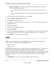
...Master, select either 1 or 2 from the stack list. 4. Stack Management The Stack Management screen allows network managers to assign specific Unit numbers to stacking members or enable the software to take effect. Force Master - See "Reset" for the new settings ... take effect after reset. To configure Stack Management: 1. Possible values are 1-6. Forces the selection of the Stack. GS700TS Smart Switch Software Administration Manual - Select the Master Election mode. 3. Displays the stacking member's current Unit number. Managing System Settings v1.0, June ...
...Master, select either 1 or 2 from the stack list. 4. Stack Management The Stack Management screen allows network managers to assign specific Unit numbers to stacking members or enable the software to take effect. Force Master - See "Reset" for the new settings ... take effect after reset. To configure Stack Management: 1. Possible values are 1-6. Forces the selection of the Stack. GS700TS Smart Switch Software Administration Manual - Select the Master Election mode. 3. Displays the stacking member's current Unit number. Managing System Settings v1.0, June ...
GS7xxTS User Manual
Page 52
...SNMP agents maintain a list of variables that are defined for the new settings to manage the device. The SNMP agent defines the MIB specification format, as well as the format used to take effect. After Reset - See "Reset" for managing network devices. SNMP v3 ...information over the network. Click APPLY to the SNMP agents. Reset the device for SNMPv3, including: • Authentication - GS700TS Smart Switch Software Administration Manual • Unit No. Click APPLY. Provides data integrity and data origin authentication. 3-17 v1.0, June 2009 Managing System...
...SNMP agents maintain a list of variables that are defined for the new settings to manage the device. The SNMP agent defines the MIB specification format, as well as the format used to take effect. After Reset - See "Reset" for managing network devices. SNMP v3 ...information over the network. Click APPLY to the SNMP agents. Reset the device for SNMPv3, including: • Authentication - GS700TS Smart Switch Software Administration Manual • Unit No. Click APPLY. Provides data integrity and data origin authentication. 3-17 v1.0, June 2009 Managing System...

GS7xxTS User Manual
Page 55
... whether traps are sent to remove the entry. The SNMPv1/v2 Trap Configuration screen displays: Managing System Settings v1.0, June 2009 3-20 Click DELETE to specific users, and the trap type sent. To add a new SNMP community: 1. Click System > SNMP > SNMPv1/v2 > Community Configuration. Click System > SNMP > SNMPv1/v2 > Community Configuration... Filtering • Defining Trap Generation Parameters • Providing Access Control Checks To configure SNMPv1/v2 trap station management: 1. Click APPLY to update the device. GS700TS Smart Switch Software Administration Manual 5.
... whether traps are sent to remove the entry. The SNMPv1/v2 Trap Configuration screen displays: Managing System Settings v1.0, June 2009 3-20 Click DELETE to specific users, and the trap type sent. To add a new SNMP community: 1. Click System > SNMP > SNMPv1/v2 > Community Configuration. Click System > SNMP > SNMPv1/v2 > Community Configuration... Filtering • Defining Trap Generation Parameters • Providing Access Control Checks To configure SNMPv1/v2 trap station management: 1. Click APPLY to update the device. GS700TS Smart Switch Software Administration Manual 5.

GS7xxTS User Manual
Page 63
...- Groups allow network managers to assign access rights to which access control rules are : - Enter the user-defined group to specific device features or feature aspects. Select the SNMP version associated with the group. SNMPv2 - The possible field values are applied. ...28 The SNMPv3 Groups screen displays: Figure 3-15 The SNMPv3 Groups screen contains the following fields: • Group Name - GS700TS Smart Switch Software Administration Manual To remove an SNMPv3 community: 1. SNMPv1 is defined for creating SNMP groups and assigning SNMP access control privileges ...
...- Groups allow network managers to assign access rights to which access control rules are : - Enter the user-defined group to specific device features or feature aspects. Select the SNMP version associated with the group. SNMPv2 - The possible field values are applied. ...28 The SNMPv3 Groups screen displays: Figure 3-15 The SNMPv3 Groups screen contains the following fields: • Group Name - GS700TS Smart Switch Software Administration Manual To remove an SNMPv3 community: 1. SNMPv1 is defined for creating SNMP groups and assigning SNMP access control privileges ...

GS7xxTS User Manual
Page 68
GS700TS Smart Switch Software Administration Manual • Authentication Notifications - Disables the device from sending authentication failure notifications. - This is the default value. 2. Select either Enable or Disable...• Providing Access Control Checks To define trap station management: 1. The possible field values are sent to send authentication failure notifications. Enables the device to specific users, and the trap type sent. Disable - Select either Enable or Disable in the SNMP Notifications provided field. 3. The SNMPv3 Trap Configuration screen displays...
GS700TS Smart Switch Software Administration Manual • Authentication Notifications - Disables the device from sending authentication failure notifications. - This is the default value. 2. Select either Enable or Disable...• Providing Access Control Checks To define trap station management: 1. The possible field values are sent to send authentication failure notifications. Enables the device to specific users, and the trap type sent. Disable - Select either Enable or Disable in the SNMP Notifications provided field. 3. The SNMPv3 Trap Configuration screen displays...

GS7xxTS User Manual
Page 78
... the interface. 3-43 v1.0, June 2009 Managing System Settings GS700TS Smart Switch Software Administration Manual LLDP Port Settings The LLDP Port Settings screen allows network administrators to define LLDP port settings, including the port type, the LLDP port state, and the type of the interface. Displays the specific interface for which LLDP parameters are defined. • Admin Status...
... the interface. 3-43 v1.0, June 2009 Managing System Settings GS700TS Smart Switch Software Administration Manual LLDP Port Settings The LLDP Port Settings screen allows network administrators to define LLDP port settings, including the port type, the LLDP port state, and the type of the interface. Displays the specific interface for which LLDP parameters are defined. • Admin Status...