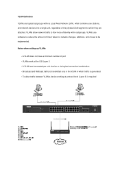
Shared access to the Internet for multiple VLANs - No routing
Page 2
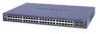
...attached. VLANs allow traffic between VLAN a device working at protocol level (Layer 3) is required 24 Port 10/100/1000 Mbps Smart Switch 1 3 5 7 9 11 13 15 17 19 21 23 LINK/ACT SPD Green = ... 23F 24F SFP LINK SFP LINK MODEL GS724T A uto™ U pli nk Fa c to be implemented. Notes when setting-up VLANs • A VLAN does not have a minimum number of port • ... devices into a single unit, regardless of time it takes for network changes, additions, and moves to r y Defaults ProSafe VPN Wireless ADSL Gateway MODEL DGFV 338 PWR TEST IN TERN ET 10 0 D SL LINK/ACT LOC AL 10 0...
...attached. VLANs allow traffic between VLAN a device working at protocol level (Layer 3) is required 24 Port 10/100/1000 Mbps Smart Switch 1 3 5 7 9 11 13 15 17 19 21 23 LINK/ACT SPD Green = ... 23F 24F SFP LINK SFP LINK MODEL GS724T A uto™ U pli nk Fa c to be implemented. Notes when setting-up VLANs • A VLAN does not have a minimum number of port • ... devices into a single unit, regardless of time it takes for network changes, additions, and moves to r y Defaults ProSafe VPN Wireless ADSL Gateway MODEL DGFV 338 PWR TEST IN TERN ET 10 0 D SL LINK/ACT LOC AL 10 0...
GS7xxTS Hardware manual
Page 5
... the Site 2-29 Step 2: Installing the Switch 2-30 Installing the Switch on a Flat Surface 2-30 Installing the Switch in a Rack 2-30 Step 3: Checking the Installation 2-31 Step 4: Connecting Devices to the Switch 2-32 Step 5: Installing an SFP GBIC Module 2-32 Step 6: Installing a Device... 2-33 Step 7: Applying AC Power 2-34 Step 8: Managing the Switch through a Web Browser or the PC Utility for Initial Configuration ...2-35 Chapter 3 Physical Description Front and Back Panel Configuration 3-19 GS724TS Front and Back Panels 3-19 GS748TS...
... the Site 2-29 Step 2: Installing the Switch 2-30 Installing the Switch on a Flat Surface 2-30 Installing the Switch in a Rack 2-30 Step 3: Checking the Installation 2-31 Step 4: Connecting Devices to the Switch 2-32 Step 5: Installing an SFP GBIC Module 2-32 Step 6: Installing a Device... 2-33 Step 7: Applying AC Power 2-34 Step 8: Managing the Switch through a Web Browser or the PC Utility for Initial Configuration ...2-35 Chapter 3 Physical Description Front and Back Panel Configuration 3-19 GS724TS Front and Back Panels 3-19 GS748TS...
GS7xxTS Hardware manual
Page 6
... ...3-22 System LEDs ...3-22 Device Hardware Interfaces 3-23 RJ-45 Ports ...3-23 SFP GBIC Module 3-24 Factory Defaults Button 3-24 Appendix A Troubleshooting Troubleshooting Chart A-1 Additional Troubleshooting Suggestions A-2 Network Adapter Cards A-2 Configuration ...A-2 Switch Integrity ...A-2 Auto-negotiation ...A-3 Appendix B Technical Specifications Network Protocol and Standards Compatibility B-1 Management ...B-1 Interface ...B-1 LEDs ...B-1 Performance Specifications B-2 Power Supply ...B-2 Physical Specifications B-2 Environmental...
... ...3-22 System LEDs ...3-22 Device Hardware Interfaces 3-23 RJ-45 Ports ...3-23 SFP GBIC Module 3-24 Factory Defaults Button 3-24 Appendix A Troubleshooting Troubleshooting Chart A-1 Additional Troubleshooting Suggestions A-2 Network Adapter Cards A-2 Configuration ...A-2 Switch Integrity ...A-2 Auto-negotiation ...A-3 Appendix B Technical Specifications Network Protocol and Standards Compatibility B-1 Management ...B-1 Interface ...B-1 LEDs ...B-1 Performance Specifications B-2 Power Supply ...B-2 Physical Specifications B-2 Environmental...
GS7xxTS Hardware manual
Page 10
...ports with four additional SFP combo fiber ports. • GS748TS - You can stack together up to eliminate bottlenecks, boost performance, and increase productivity. This chapter serves as a stand-alone. For example: • Connecting switches to each other with four additional SFP combo fiber ports. Chapter 1 Introduction The NETGEAR Smart Switch... ports and want the power of Gigabit connectivity to six units for a maximunm of 192 10/100 ports or you can use out of the box. You can make high-speed connections using the Gigabit ports. This product offers support for 48 ports...
...ports with four additional SFP combo fiber ports. • GS748TS - You can stack together up to eliminate bottlenecks, boost performance, and increase productivity. This chapter serves as a stand-alone. For example: • Connecting switches to each other with four additional SFP combo fiber ports. Chapter 1 Introduction The NETGEAR Smart Switch... ports and want the power of Gigabit connectivity to six units for a maximunm of 192 10/100 ports or you can use out of the box. You can make high-speed connections using the Gigabit ports. This product offers support for 48 ports...
GS7xxTS Hardware manual
Page 11
...switch port connected to the highest speed. The GS700TS Smart Switch can view the switch's many features and use them in half- These features provide better understanding and control of Ethernet, Fast Ethernet, or Gigabit Ethernet devices. This capability makes the switch ideal for fiber connections using SFP...latency for the observation, configuration, and control of the network. The NETGEAR Smart Switch can provide 2000 Mbps throughput. Introduction v1.0, November 2007 1-14 or full-duplex mode. All ports can automatically negotiate to the server or PC can be free-standing,...
...switch port connected to the highest speed. The GS700TS Smart Switch can view the switch's many features and use them in half- These features provide better understanding and control of Ethernet, Fast Ethernet, or Gigabit Ethernet devices. This capability makes the switch ideal for fiber connections using SFP...latency for the observation, configuration, and control of the network. The NETGEAR Smart Switch can provide 2000 Mbps throughput. Introduction v1.0, November 2007 1-14 or full-duplex mode. All ports can automatically negotiate to the server or PC can be free-standing,...

GS7xxTS Hardware manual
Page 12
... devices are the four 10/100/1000M auto-sensing Giga switching ports on each device. GS700TS Hardware Installation Guide Figure 1-1 Switch Features The following list identifies the key features of the NETGEAR Smart Switch. • 24/48 RJ-45 10/100/1000M auto-sensing Giga switching ports. • Four Small Form-factor Pluggable (SFP) GBIC slots, which function as combo...
... devices are the four 10/100/1000M auto-sensing Giga switching ports on each device. GS700TS Hardware Installation Guide Figure 1-1 Switch Features The following list identifies the key features of the NETGEAR Smart Switch. • 24/48 RJ-45 10/100/1000M auto-sensing Giga switching ports. • Four Small Form-factor Pluggable (SFP) GBIC slots, which function as combo...

GS7xxTS Hardware manual
Page 16
... Rack-mount installations - Use a 19-inch (48.3-centimeter) EIA standard equipment rack that allows access to the front panel RJ-45 ports, the ability to view the front panel LEDs, and easy safe access access to the Switch Step 5: Installing an SFP GBIC Module Step 6: Installing a Device Step ...7: Applying AC Power Step 8: Managing the Switch through a Web Browser or the PC Utility for your NETGEAR Smart Switch. v1.0, ...
... Rack-mount installations - Use a 19-inch (48.3-centimeter) EIA standard equipment rack that allows access to the front panel RJ-45 ports, the ability to view the front panel LEDs, and easy safe access access to the Switch Step 5: Installing an SFP GBIC Module Step 6: Installing a Device Step ...7: Applying AC Power Step 8: Managing the Switch through a Web Browser or the PC Utility for your NETGEAR Smart Switch. v1.0, ...
GS7xxTS Hardware manual
Page 19
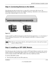
... Guide Step 4: Connecting Devices to the Switch The following procedure describes how to install an SFP Gigabit Ethernet module in the switch's Gigabit module bay. The NETGEAR Smart Switch contains Auto Uplink™ technology, which ...allows you do not plan to install an SFP GBIC module at this time, skip this procedure. Note: Ethernet specifications limit the cable length between the switch and the attached device to an RJ-45 network port on the Switch...
... Guide Step 4: Connecting Devices to the Switch The following procedure describes how to install an SFP Gigabit Ethernet module in the switch's Gigabit module bay. The NETGEAR Smart Switch contains Auto Uplink™ technology, which ...allows you do not plan to install an SFP GBIC module at this time, skip this procedure. Note: Ethernet specifications limit the cable length between the switch and the attached device to an RJ-45 network port on the Switch...

GS7xxTS Hardware manual
Page 23
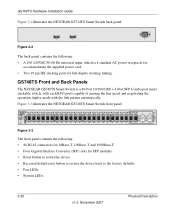
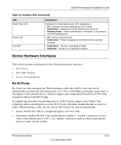
... topics include: • GS724TS Front and Back Panels • GS748TS Front and Back Panels • LED Designations • Device Hardware Interfaces Front and Back Panel Configuration GS724TS Front and Back Panels The NETGEAR GS724TS Smart Switch is a 24-Port 10/100/1000 + 4-Port SFP Combo port switch, with each RJ45 ports capable of sensing the line speed and negotiating the...
... topics include: • GS724TS Front and Back Panels • GS748TS Front and Back Panels • LED Designations • Device Hardware Interfaces Front and Back Panel Configuration GS724TS Front and Back Panels The NETGEAR GS724TS Smart Switch is a 24-Port 10/100/1000 + 4-Port SFP Combo port switch, with each RJ45 ports capable of sensing the line speed and negotiating the...
GS7xxTS Hardware manual
Page 24
.... • System LEDs. 3-20 v1.0, November 2007 Physical Description Figure 3-3 illustrates the NETGEAR GS748TS Smart Switch front panel: Figure 3-3 The front panel contains the following : • A 100-240VAC/50-60 Hz universal input, which is a 48-Port 10/100/1000 + 4-Port SFP Combo port smart stackable switch, with each RJ45 ports capable of sensing the line speed and negotiating the operation duplex mode...
.... • System LEDs. 3-20 v1.0, November 2007 Physical Description Figure 3-3 illustrates the NETGEAR GS748TS Smart Switch front panel: Figure 3-3 The front panel contains the following : • A 100-240VAC/50-60 Hz universal input, which is a 48-Port 10/100/1000 + 4-Port SFP Combo port smart stackable switch, with each RJ45 ports capable of sensing the line speed and negotiating the operation duplex mode...
GS7xxTS Hardware manual
Page 26
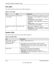
...Port LEDs Port LED 24/48-10/100/1000 Ports Link/ACT LED - One LED/ SFP Link/ACT LED Port Designation • Off - Packet transmission or reception is established on the port at 100Mbps. • Solid Yellow - Table 3-2. Indicates the Up stacking port link is up. • Flashing Green - A valid 10Mbps link is occurring on the port... is established on the port at 10Mbps. • Off - No 10/100Mbps link is occurring on the port. • Solid Green - System LEDs LED Stack ID LED - Switch acts as a master unit in a stack of switches. • Solid Green...
...Port LEDs Port LED 24/48-10/100/1000 Ports Link/ACT LED - One LED/ SFP Link/ACT LED Port Designation • Off - Packet transmission or reception is established on the port at 100Mbps. • Solid Yellow - Table 3-2. Indicates the Up stacking port link is up. • Flashing Green - A valid 10Mbps link is occurring on the port... is established on the port at 10Mbps. • Off - No 10/100Mbps link is occurring on the port. • Solid Green - System LEDs LED Stack ID LED - Switch acts as a master unit in a stack of switches. • Solid Green...
GS7xxTS Hardware manual
Page 27
... Flashing Green - or full-duplex) of the attached device. This technology allows attaching devices to a router, switch, or hub). When inserting a cable into an RJ-45 port, the switch automatically ascertains the maximum speed (10 or 100 or 1000 Mbps) and duplex mode (half- GS700TS Hardware Installation... (such as when connecting the port to a PC) or an "uplink" connection (such as when connecting the port to the RJ-45 ports with an 8-pin RJ-45 plug. To simplify the procedure for the following hardware interfaces: • RJ-45 Ports • SFP GBIC Module • Factory Defaults...
... Flashing Green - or full-duplex) of the attached device. This technology allows attaching devices to a router, switch, or hub). When inserting a cable into an RJ-45 port, the switch automatically ascertains the maximum speed (10 or 100 or 1000 Mbps) and duplex mode (half- GS700TS Hardware Installation... (such as when connecting the port to a PC) or an "uplink" connection (such as when connecting the port to the RJ-45 ports with an 8-pin RJ-45 plug. To simplify the procedure for the following hardware interfaces: • RJ-45 Ports • SFP GBIC Module • Factory Defaults...

GS7xxTS Hardware manual
Page 28
... example, both connectors are plugged in at the same time, the fiber port becomes active. Factory Defaults Button The Smart Switch has a Factory default button to enable clearing the current configuration and returning the... device back to use crossover or straightthrough cables when attaching devices. The SFP GBIC bay accommodates a standard SFP GBIC module. SFP GBIC Module The GBIC module bays accommodate standard SFP GBIC modules, such as the AGM731F, AGM732F, or AGM733 from NETGEAR...
... example, both connectors are plugged in at the same time, the fiber port becomes active. Factory Defaults Button The Smart Switch has a Factory default button to enable clearing the current configuration and returning the... device back to use crossover or straightthrough cables when attaching devices. The SFP GBIC bay accommodates a standard SFP GBIC module. SFP GBIC Module The GBIC module bays accommodate standard SFP GBIC modules, such as the AGM731F, AGM732F, or AGM733 from NETGEAR...
GS7xxTS Hardware manual
Page 32
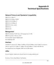
... device: Power, Stack Master, Unit Number B-1 v1.0, November 2007 LEDs Per port (Gigabit): Link/Activity, Speed, Stack (for SFP module. Appendix B Technical Specifications Network Protocol and Standards Compatibility IEEE 802.3i 10Base-T IEEE 802.3u 100Base-TX,FX IEEE 802.3ab 1000Base-T IEEE 802.... 802.1x IEEE 802.1D Management IEEE 802.1Q Static VLAN (Up to 128 ranging from 2 to 4K) IEEE 802.1p Class of Service (CoS) Port-based QoS (options High/Normal) Port Trunking LACP Interface 24/48 RJ-45 connectors for 10Base-T,100Base-TX and 1000Base-(Auto Uplink™ on all...
... device: Power, Stack Master, Unit Number B-1 v1.0, November 2007 LEDs Per port (Gigabit): Link/Activity, Speed, Stack (for SFP module. Appendix B Technical Specifications Network Protocol and Standards Compatibility IEEE 802.3i 10Base-T IEEE 802.3u 100Base-TX,FX IEEE 802.3ab 1000Base-T IEEE 802.... 802.1x IEEE 802.1D Management IEEE 802.1Q Static VLAN (Up to 128 ranging from 2 to 4K) IEEE 802.1p Class of Service (CoS) Port-based QoS (options High/Normal) Port Trunking LACP Interface 24/48 RJ-45 connectors for 10Base-T,100Base-TX and 1000Base-(Auto Uplink™ on all...

GS7xxTS Hardware manual
Page 34
Electromagnetic Immunity EN 55022 (CISPR 22), Class A Safety CE mark, commercial UL listed (UL 1950) / CUL IEC950 / EN60950 Modules AGM731F 1000Base-SX SFP GBIC for multimode fiber AGM732F 1000Base-LX SFP GBIC for single mode fiber AGM733 1000Base-LZ GBIC for long haul single mode fiber B-3 Technical Specifications v1.0, November 2007
Electromagnetic Immunity EN 55022 (CISPR 22), Class A Safety CE mark, commercial UL listed (UL 1950) / CUL IEC950 / EN60950 Modules AGM731F 1000Base-SX SFP GBIC for multimode fiber AGM732F 1000Base-LX SFP GBIC for single mode fiber AGM733 1000Base-LZ GBIC for long haul single mode fiber B-3 Technical Specifications v1.0, November 2007
GS7xxTS Hardware manual
Page 36
...IEEE 802.3u 1-2 IEEE 802.3x 1-2, 1-3 IEEE 802.3z 1-2 IEEE Standards 1-2 IEEE-compliant 1-2 Installation Guide 1-4 Installing an SFP GBIC Module 4-16 Installing the Switch 4-14 Internal Power Supply 1-3 L LED Designations 2-8 Link/ACT LED 2-8 Low Latency 1-2 M MAC 1-3 MAX POE LED 2-9 ... 4-14 Reset Button 2-5, 2-7 RJ-45 1-2 RJ-45 Ports 2-9 Rubber Footpad 4-14 Rubber footpads 1-4 S SFP GBIC Module 2-10 SFP Link/ACT LED 2-8 SFP Module Bay 4-17 Site Requirements 4-13 Small Form-factor Pluggable (SFP) 1-2 Smart Switch Resource CD 1-4 SmartWizard Discovery 1-2 Straight-through 2-9 Support Information...
...IEEE 802.3u 1-2 IEEE 802.3x 1-2, 1-3 IEEE 802.3z 1-2 IEEE Standards 1-2 IEEE-compliant 1-2 Installation Guide 1-4 Installing an SFP GBIC Module 4-16 Installing the Switch 4-14 Internal Power Supply 1-3 L LED Designations 2-8 Link/ACT LED 2-8 Low Latency 1-2 M MAC 1-3 MAX POE LED 2-9 ... 4-14 Reset Button 2-5, 2-7 RJ-45 1-2 RJ-45 Ports 2-9 Rubber Footpad 4-14 Rubber footpads 1-4 S SFP GBIC Module 2-10 SFP Link/ACT LED 2-8 SFP Module Bay 4-17 Site Requirements 4-13 Small Form-factor Pluggable (SFP) 1-2 Smart Switch Resource CD 1-4 SmartWizard Discovery 1-2 Straight-through 2-9 Support Information...