
FS728TP Hardware manual
Page 13
FS728TP Hardware Installation Guide • Active flow control to PD. Smart Power Managed function handles the power of each port in the event of the NETGEAR Smart Switch Figure 1-2 Introduction v1.0, November 2007 1-16 Package Contents Figure 1-2 shows the package contents of limited available power. - Support 24-Port POE function, 15.4W for 12 ports , 8W for 24 ports , Total 192W for...
FS728TP Hardware Installation Guide • Active flow control to PD. Smart Power Managed function handles the power of each port in the event of the NETGEAR Smart Switch Figure 1-2 Introduction v1.0, November 2007 1-16 Package Contents Figure 1-2 shows the package contents of limited available power. - Support 24-Port POE function, 15.4W for 12 ports , 8W for 24 ports , Total 192W for...
FS728TP Hardware manual
Page 24
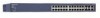
...8226; Solid Yellow - Physical Description v1.0, November 2007 3-22 FAN is disconnected. • Solid Green - FAN has failed. • Off - All ports support only Unshielded Twisted-Pair (UTP) cable terminated with either ...into the switch's RJ-45 port, the switch automatically: • Senses whether the cable is available. • Flashing Yellow - To simplify the procedure for attaching devices, all RJ-45 ports support Auto Uplink. FS728TP Hardware ...into an RJ-45 port, the switch automatically ascertains the maximum speed (10 or 100 or 1000 Mbps) and duplex mode (half-
...8226; Solid Yellow - Physical Description v1.0, November 2007 3-22 FAN is disconnected. • Solid Green - FAN has failed. • Off - All ports support only Unshielded Twisted-Pair (UTP) cable terminated with either ...into the switch's RJ-45 port, the switch automatically: • Senses whether the cable is available. • Flashing Yellow - To simplify the procedure for attaching devices, all RJ-45 ports support Auto Uplink. FS728TP Hardware ...into an RJ-45 port, the switch automatically ascertains the maximum speed (10 or 100 or 1000 Mbps) and duplex mode (half-
FS728TP Hardware manual
Page 32
... Installation 4-15 Class of Service 1-2 Combo Port 2-10 Combo Ports 1-2 Connecting Devices to the Switch 4-16 Copper 1-1 Crossover 2-9 D Default IP Address 4-18 Default Reset Button 2-5, 2-7 Device Hardware Interfaces 2-9 Duplex Mode 2-9 E Example of Desktop Switching 3-12 F Factory Default Button 2-10 Factory Defaults 2-5 Fan LED 2-9 Fiber Connectivity 1-1 Flat Surface 4-14 Full-duplex 1-2 G GBIC 1-2, 2-10 Gigabit Ports 1-1 H High-speed Servers 1-1 v1.0, November...
... Installation 4-15 Class of Service 1-2 Combo Port 2-10 Combo Ports 1-2 Connecting Devices to the Switch 4-16 Copper 1-1 Crossover 2-9 D Default IP Address 4-18 Default Reset Button 2-5, 2-7 Device Hardware Interfaces 2-9 Duplex Mode 2-9 E Example of Desktop Switching 3-12 F Factory Default Button 2-10 Factory Defaults 2-5 Fan LED 2-9 Fiber Connectivity 1-1 Flat Surface 4-14 Full-duplex 1-2 G GBIC 1-2, 2-10 Gigabit Ports 1-1 H High-speed Servers 1-1 v1.0, November...
