
Installation Guide
Page 3
...-211-2069 − Japan: 0031-1-26133 − Germany: 0130-8-23776 • Fax: − U.S./Canada: 510-498-2609 World Wide Web NETGEAR maintains a World Wide Web Home Page that are required. Voluntary Control Council for Interference (VCCI) Statement Voluntary Control Council for Interference (VCCI) Statement ...areas. Customer Support For assistance with installing and configuring your NETGEAR systems or with post-installation questions or problems, contact your point of this equipment is in the 1st category (information equipment to be caused to equipment such as Mosaic or ...
...-211-2069 − Japan: 0031-1-26133 − Germany: 0130-8-23776 • Fax: − U.S./Canada: 510-498-2609 World Wide Web NETGEAR maintains a World Wide Web Home Page that are required. Voluntary Control Council for Interference (VCCI) Statement Voluntary Control Council for Interference (VCCI) Statement ...areas. Customer Support For assistance with installing and configuring your NETGEAR systems or with post-installation questions or problems, contact your point of this equipment is in the 1st category (information equipment to be caused to equipment such as Mosaic or ...
Installation Guide
Page 7
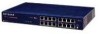
... configuration errors. • Stackable chassis equipped with as few as 8 ports and growing the network as required by stacking up to four hubs for a total of the 100BASE-T ports (Port 8 on the Model FE508 hub and Port 16 on the Model FE516 hub) for connection to provide ...network traffic status for the hub. − Normal/Uplink push button for interoperation with all 100BASE-TX Fast Ethernet (100 Mbps) products. • Stackable architecture allows starting with : − 8 or 16 fast 100BASE-TX ports to provide fast information exchange, ...
... configuration errors. • Stackable chassis equipped with as few as 8 ports and growing the network as required by stacking up to four hubs for a total of the 100BASE-T ports (Port 8 on the Model FE508 hub and Port 16 on the Model FE516 hub) for connection to provide ...network traffic status for the hub. − Normal/Uplink push button for interoperation with all 100BASE-TX Fast Ethernet (100 Mbps) products. • Stackable architecture allows starting with : − 8 or 16 fast 100BASE-TX ports to provide fast information exchange, ...

Installation Guide
Page 10
... and the Uplink (MDI) RJ-45 connector. CAUTION: 100 Mbps operation requires the use of the Model FE508 hub provides 8 RJ-45 100BASE-TX ports and the Model FE516 provides 16 RJ-45 100BASE-TX ports. RJ-45 100BASE-TX Ports The front panel of Category 5 UTP wiring...) copper wiring (100BASE-TX networks require only 2-pair). Installation Guide for the Model FE508 and FE516 Fast Ethernet Hubs Table 2-1 describes each RJ-45 port connection. Table B-1 provides the pin out information for more information on the port. * Link and RX LEDs are positioned at the top corners of each LED...
... and the Uplink (MDI) RJ-45 connector. CAUTION: 100 Mbps operation requires the use of the Model FE508 hub provides 8 RJ-45 100BASE-TX ports and the Model FE516 provides 16 RJ-45 100BASE-TX ports. RJ-45 100BASE-TX Ports The front panel of Category 5 UTP wiring...) copper wiring (100BASE-TX networks require only 2-pair). Installation Guide for the Model FE508 and FE516 Fast Ethernet Hubs Table 2-1 describes each RJ-45 port connection. Table B-1 provides the pin out information for more information on the port. * Link and RX LEDs are positioned at the top corners of each LED...

Installation Guide
Page 11
...Ports 8 and 16 for Normal wiring if the remote end of the cable is connected to Appendix C, "Fast Ethernet and Cabling Guidelines," for information on the hubs cannot be configured for Uplink wiring. Ports 8 and 16 are configured for Uplink wiring. If you are connecting the same type of devices. Installation... Guide for the Model FE508 and FE516 Fast Ethernet Hubs Normal/Uplink Push Button The Normal/Uplink push button (see Figure 2-3) on the front panel of the hub allows you to another Normal port, you must use an RJ-45 cross-over ...
...Ports 8 and 16 for Normal wiring if the remote end of the cable is connected to Appendix C, "Fast Ethernet and Cabling Guidelines," for information on the hubs cannot be configured for Uplink wiring. Ports 8 and 16 are configured for Uplink wiring. If you are connecting the same type of devices. Installation... Guide for the Model FE508 and FE516 Fast Ethernet Hubs Normal/Uplink Push Button The Normal/Uplink push button (see Figure 2-3) on the front panel of the hub allows you to another Normal port, you must use an RJ-45 cross-over ...

Installation Guide
Page 13
... Chapter 3, "Installation," for the Model FE508 and FE516 Fast Ethernet Hubs Cascade Connectors The Model FE508 and Model FE516 Fast Ethernet hubs can consist of any combination of Model FE508 and Model FE516 hubs daisy-chained together using a NETGEARsupplied cascade cable. Cascade cabling two hubs 2-6 Physical Description Refer to each hub. The cascade cable daisy chains between the...
... Chapter 3, "Installation," for the Model FE508 and FE516 Fast Ethernet Hubs Cascade Connectors The Model FE508 and Model FE516 Fast Ethernet hubs can consist of any combination of Model FE508 and Model FE516 hubs daisy-chained together using a NETGEARsupplied cascade cable. Cascade cabling two hubs 2-6 Physical Description Refer to each hub. The cascade cable daisy chains between the...

Installation Guide
Page 15
...Between 5% and 85% noncondensing. Adequate airflow in room or wiring closet. Minimum 12 inches (19.68 cm) front and back for each NETGEAR 100BASE-T hub. Standard 19-inch (48.26 cm) EIA equipment rack, with supplied mounting bracket hardware, 1.0 EIA rack-mount spaces needed for service ...access and maintenance. Chapter 3 Installation This chapter provides information and procedures on all sides for cables and wiring hardware such as punchdown ...
...Between 5% and 85% noncondensing. Adequate airflow in room or wiring closet. Minimum 12 inches (19.68 cm) front and back for each NETGEAR 100BASE-T hub. Standard 19-inch (48.26 cm) EIA equipment rack, with supplied mounting bracket hardware, 1.0 EIA rack-mount spaces needed for service ...access and maintenance. Chapter 3 Installation This chapter provides information and procedures on all sides for cables and wiring hardware such as punchdown ...

Installation Guide
Page 18
... Figure 3-1). The EIA/TIA 568-A standard recommends the installation of termination. Installation Guide for the Model FE508 and FE516 Fast Ethernet Hubs Installing a NETGEAR 100BASE-T Hub This section provides information and instructions for proper wire placement according to the specifications: • Certification. There are certain guidelines to follow these steps: 1. To minimize crosstalk noise, maintain...
... Figure 3-1). The EIA/TIA 568-A standard recommends the installation of termination. Installation Guide for the Model FE508 and FE516 Fast Ethernet Hubs Installing a NETGEAR 100BASE-T Hub This section provides information and instructions for proper wire placement according to the specifications: • Certification. There are certain guidelines to follow these steps: 1. To minimize crosstalk noise, maintain...
Installation Guide
Page 21
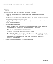
... the supplied cascade cable provide the ability to stack and link up to four hubs. Installation Guide for the Model FE508 and FE516 Fast Ethernet Hubs Installing Multiple Hubs This section provides you can expand the network to a maximum of 64 100BASE-TX ports. This cable is likely... to cause performance degradation or network problems. Replacement cables are available from NETGEAR at the contact numbers listed in a stack. CAUTION: Use only the NETGEAR-supplied cascade cable. By stacking hubs, you with information about installing a stack of...
... the supplied cascade cable provide the ability to stack and link up to four hubs. Installation Guide for the Model FE508 and FE516 Fast Ethernet Hubs Installing Multiple Hubs This section provides you can expand the network to a maximum of 64 100BASE-TX ports. This cable is likely... to cause performance degradation or network problems. Replacement cables are available from NETGEAR at the contact numbers listed in a stack. CAUTION: Use only the NETGEAR-supplied cascade cable. By stacking hubs, you with information about installing a stack of...

Installation Guide
Page 25
... hub and network. Verifying the LED Conditions At power on, verify the following LED conditions: • Power LED is on. • Link LED on each connected port is lit. • Terminator LED on the rear panel is: − Lit for a description and location of the LEDs). Chapter 4 Troubleshooting This chapter provides information... about troubleshooting the hub.
... hub and network. Verifying the LED Conditions At power on, verify the following LED conditions: • Power LED is on. • Link LED on each connected port is lit. • Terminator LED on the rear panel is: − Lit for a description and location of the LEDs). Chapter 4 Troubleshooting This chapter provides information... about troubleshooting the hub.

Installation Guide
Page 35
... Mbps data transmission. Figure B-1. Connector Pin Assignments B-1 RJ-45 connector Table B-1. Table B-1 provides the pin out information for the Normal (MDI-X) RJ-45 connector and the pin out information for the Model FE508 and Model FE516 Fast Ethernet hubs. The RJ-45 connector accepts two- Output Transmit Data - 3 Output Transmit Data + Input Receive Data...
... Mbps data transmission. Figure B-1. Connector Pin Assignments B-1 RJ-45 connector Table B-1. Table B-1 provides the pin out information for the Normal (MDI-X) RJ-45 connector and the pin out information for the Model FE508 and Model FE516 Fast Ethernet hubs. The RJ-45 connector accepts two- Output Transmit Data - 3 Output Transmit Data + Input Receive Data...