Installation Guide
Page 11
...-T network. By installing the Model FE104 or Model FE108 hub in your purchase of basic Ethernet • Familiarity with many users who can increase the bandwidth and improve response times. This guide describes how to support power workgroups operating at 100 ...hubs are IEEE 802.3u-based Class II repeaters that provide you can share access to centralized network devices (such as servers and printers) at 100 Mbps. Users who have the following background and experience: • Working knowledge of the NETGEAR™ Model FE104 4-port Fast Ethernet Hub or the NETGEAR Model FE108...
...-T network. By installing the Model FE104 or Model FE108 hub in your purchase of basic Ethernet • Familiarity with many users who can increase the bandwidth and improve response times. This guide describes how to support power workgroups operating at 100 ...hubs are IEEE 802.3u-based Class II repeaters that provide you can share access to centralized network devices (such as servers and printers) at 100 Mbps. Users who have the following background and experience: • Working knowledge of the NETGEAR™ Model FE104 4-port Fast Ethernet Hub or the NETGEAR Model FE108...

Installation Guide
Page 12
...Guide for the Model FE104 and Model FE108 Fast Ethernet Hubs Features The Model FE104 and Model FE108 hubs have the following key features: • IEEE 802.3u standard compliance allows interoperation with all 100BASE-TX Fast Ethernet (100 Mbps) products. • Class II compliance enables network expansion by daisy-chaining two hubs... software to configure saves time and minimizes the potential for the hub. - Normal/Uplink push button to clearly indicate the status of each port. - In the uplink mode, two hubs can be daisy-chained using simple Category 5 unshielded twisted pair (UTP) ...
...Guide for the Model FE104 and Model FE108 Fast Ethernet Hubs Features The Model FE104 and Model FE108 hubs have the following key features: • IEEE 802.3u standard compliance allows interoperation with all 100BASE-TX Fast Ethernet (100 Mbps) products. • Class II compliance enables network expansion by daisy-chaining two hubs... software to configure saves time and minimizes the potential for the hub. - Normal/Uplink push button to clearly indicate the status of each port. - In the uplink mode, two hubs can be daisy-chained using simple Category 5 unshielded twisted pair (UTP) ...

Installation Guide
Page 14
...; Data utilization percentage of the Ethernet segment in a standalone hub or a stack of the hub power supply • Collision occurrence on each port 5 = Normal/Uplink push button Figure 2-2. Installation Guide for the Model FE104 and Model FE108 Fast Ethernet Hubs 1 2 3 4 5 Pwr Col 100BASE-TX FAST ETHERNET HUB FE108 100 Mbps F AST 1 10 20 >30 Utilization % 1 2 3 4 Link/Rx...
...; Data utilization percentage of the Ethernet segment in a standalone hub or a stack of the hub power supply • Collision occurrence on each port 5 = Normal/Uplink push button Figure 2-2. Installation Guide for the Model FE104 and Model FE108 Fast Ethernet Hubs 1 2 3 4 5 Pwr Col 100BASE-TX FAST ETHERNET HUB FE108 100 Mbps F AST 1 10 20 >30 Utilization % 1 2 3 4 Link/Rx...

Installation Guide
Page 15
Installation Guide for the Model FE104 and Model FE108 Fast Ethernet Hubs Table 2-1 describes each LED on the front panel of the Model FE104 hub provides four RJ-45 100BASE-TX ports, and the Model FE108 provides eight RJ-45 100BASE-TX ports. LED descriptions Label Pwr Col Color Green Yellow Activity On...connector. There is incoming data on the network. There is data collision on the port. RJ-45 100BASE-TX Ports The front panel of the hub. The RJ-45 interface is supplied to Appendix C, "Fast Ethernet and Cabling Guidelines," for the normal (MDI-X) RJ-45 connector and the uplink...
Installation Guide for the Model FE104 and Model FE108 Fast Ethernet Hubs Table 2-1 describes each LED on the front panel of the Model FE104 hub provides four RJ-45 100BASE-TX ports, and the Model FE108 provides eight RJ-45 100BASE-TX ports. LED descriptions Label Pwr Col Color Green Yellow Activity On...connector. There is incoming data on the network. There is data collision on the port. RJ-45 100BASE-TX Ports The front panel of the hub. The RJ-45 interface is supplied to Appendix C, "Fast Ethernet and Cabling Guidelines," for the normal (MDI-X) RJ-45 connector and the uplink...

Installation Guide
Page 16
...) LEDs on the RJ-45 ports Normal/Uplink Push Button The Normal/Uplink push button on the Model FE108 hub. Installation Guide for Port 4 on the Model FE104 hub and Port 8 on the front panel of the hub, as illustrated in Figure 2-4, allows you to select uplink (MDI) or normal (MDI-X) wiring for... the Model FE104 and Model FE108 Fast Ethernet Hubs As illustrated in Figure 2-3, two LEDs are positioned at the top ...
...) LEDs on the RJ-45 ports Normal/Uplink Push Button The Normal/Uplink push button on the Model FE108 hub. Installation Guide for Port 4 on the Model FE104 hub and Port 8 on the front panel of the hub, as illustrated in Figure 2-4, allows you to select uplink (MDI) or normal (MDI-X) wiring for... the Model FE104 and Model FE108 Fast Ethernet Hubs As illustrated in Figure 2-3, two LEDs are positioned at the top ...
Installation Guide
Page 17
... (refer to use a crossover cable for daisy-chaining or cascading. If you are using one of these ports to connect to another hub. Installation Guide for the Model FE104 and Model FE108 Fast Ethernet Hubs The Normal/Uplink push button eliminates the need to Appendix C, "Fast Ethernet and Cabling Guidelines," for information on the...
... (refer to use a crossover cable for daisy-chaining or cascading. If you are using one of these ports to connect to another hub. Installation Guide for the Model FE104 and Model FE108 Fast Ethernet Hubs The Normal/Uplink push button eliminates the need to Appendix C, "Fast Ethernet and Cabling Guidelines," for information on the...
Installation Guide
Page 18
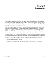
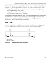
Rear panel of the Model FE108 hub 2 12 Vdc 1.2A -+ 182EA 2-6 Physical Description Installation Guide for the Model FE104 and Model FE108 Fast Ethernet Hubs 1 Key: 1 = Grounding clip 2 = DC power receptacle Figure 2-6.
Rear panel of the Model FE108 hub 2 12 Vdc 1.2A -+ 182EA 2-6 Physical Description Installation Guide for the Model FE104 and Model FE108 Fast Ethernet Hubs 1 Key: 1 = Grounding clip 2 = DC power receptacle Figure 2-6.
Installation Guide
Page 20
... your area. To qualify for repair. Installation Guide for the Model FE104 and Model FE108 Fast Ethernet Hubs Checking Package Contents This package should contain the following items: • Model FE104 or Model FE108 Fast Ethernet Hub • Rubber pads for the location of purchase and return it to NETGEAR, Inc. 3-2 Installation Refer to page iii...
... your area. To qualify for repair. Installation Guide for the Model FE104 and Model FE108 Fast Ethernet Hubs Checking Package Contents This package should contain the following items: • Model FE104 or Model FE108 Fast Ethernet Hub • Rubber pads for the location of purchase and return it to NETGEAR, Inc. 3-2 Installation Refer to page iii...

Installation Guide
Page 21
... this chapter. There are Class II devices. Installing the Hub on a Flat Surface To install the hub on installing more than one at surface, follow when installing 100 Mbps networks. Installation Guide for the Model FE104 and Model FE108 Fast Ethernet Hubs Installing a NETGEAR 100BASE-TX Hub This section provides information and instructions for wiring rules and...
... this chapter. There are Class II devices. Installing the Hub on a Flat Surface To install the hub on installing more than one at surface, follow when installing 100 Mbps networks. Installation Guide for the Model FE104 and Model FE108 Fast Ethernet Hubs Installing a NETGEAR 100BASE-TX Hub This section provides information and instructions for wiring rules and...

Installation Guide
Page 22
... "Verifying Your Installation." 1 2 Model FE108 hub Model FE108 hub 3 359EA Key: 1 = Model FE108 Fast Ethernet Hub (Normal/Uplink push button set in Uplink position) 2 = Model FE108 Fast Ethernet Hub (Normal/Uplink push button set in Figure 3-1, two hubs can be simply daisy-chained together. Installation Guide for the Model FE104 and Model FE108 Fast Ethernet Hubs Installing Multiple Hubs This section provides you...
... "Verifying Your Installation." 1 2 Model FE108 hub Model FE108 hub 3 359EA Key: 1 = Model FE108 Fast Ethernet Hub (Normal/Uplink push button set in Uplink position) 2 = Model FE108 Fast Ethernet Hub (Normal/Uplink push button set in Figure 3-1, two hubs can be simply daisy-chained together. Installation Guide for the Model FE104 and Model FE108 Fast Ethernet Hubs Installing Multiple Hubs This section provides you...

Installation Guide
Page 23
Installation Guide for the Model FE104 and Model FE108 Fast Ethernet Hubs 1 23 4 Model FS104 switch Model FE104 hub Model FE108 hub 5 Model EN108 hub 5 6 7 8 9 199EA Key: 1 = 100 Mbps connection 2 = Server 3 = FS104 10/100 Mbps switch (Normal/Uplink push button set in Normal position) 4 = 10 Mbps connection 5 = PCs with 100 Mbps connection to Fast Ethernet hub 6 = PCs with 10...
Installation Guide for the Model FE104 and Model FE108 Fast Ethernet Hubs 1 23 4 Model FS104 switch Model FE104 hub Model FE108 hub 5 Model EN108 hub 5 6 7 8 9 199EA Key: 1 = 100 Mbps connection 2 = Server 3 = FS104 10/100 Mbps switch (Normal/Uplink push button set in Normal position) 4 = 10 Mbps connection 5 = PCs with 100 Mbps connection to Fast Ethernet hub 6 = PCs with 10...

Installation Guide
Page 24
If there are any port on the hub. Installation Guide for the Model FE104 and Model FE108 Fast Ethernet Hubs Verifying Your Installation When installation is being received by any problems, refer to the hub, the following conditions should exist: • The Pwr (power) LED on the front panel is on. • The Link/Rx LED...
If there are any port on the hub. Installation Guide for the Model FE104 and Model FE108 Fast Ethernet Hubs Verifying Your Installation When installation is being received by any problems, refer to the hub, the following conditions should exist: • The Pwr (power) LED on the front panel is on. • The Link/Rx LED...
Installation Guide
Page 26
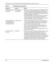
...the network simultaneously. Collisions are normal on Ethernet networks and occur when two or more computers transmit data on the front panel. Installation Guide for excessive collisions. 4-2 Troubleshooting Verify that the network adapter card is100 Mbps capable and that the proper cable is not lit after ...off or intermittent Problems with Port 4 Link/Rx LED off on the Model FE104 hub or with Port 8 on the Model FE108 hub Col (collision) LED blinking Col LED on . Computers that the computer and hub are other MDI-wired device, make sure the Normal/Uplink push button is power...
...the network simultaneously. Collisions are normal on Ethernet networks and occur when two or more computers transmit data on the front panel. Installation Guide for excessive collisions. 4-2 Troubleshooting Verify that the network adapter card is100 Mbps capable and that the proper cable is not lit after ...off or intermittent Problems with Port 4 Link/Rx LED off on the Model FE104 hub or with Port 8 on the Model FE108 hub Col (collision) LED blinking Col LED on . Computers that the computer and hub are other MDI-wired device, make sure the Normal/Uplink push button is power...

Installation Guide
Page 28
.... By adding a NETGEAR Model SW502 Ethernet Switch that has one 10 Mbps port and one server on both hubs) 4 = Server 188EA Figure 5-1. Installation Guide for the Model FE104 and Model FE108 Fast Ethernet Hubs 100BASE-TX Shared Repeater In the configuration for 100BASE-TX shared repeaters, the Model FE104 and Model FE108 hubs are connected...
.... By adding a NETGEAR Model SW502 Ethernet Switch that has one 10 Mbps port and one server on both hubs) 4 = Server 188EA Figure 5-1. Installation Guide for the Model FE104 and Model FE108 Fast Ethernet Hubs 100BASE-TX Shared Repeater In the configuration for 100BASE-TX shared repeaters, the Model FE104 and Model FE108 hubs are connected...

Installation Guide
Page 29
Installation Guide for the Model FE104 and Model FE108 Fast Ethernet Hubs 7 12 3 Model FE104 hub 4 56 Model SW502 switch 1 2 Model EN516 hub Model EN516 hub Model EN516 hub 8 8 7 7 217EA Key: 1 = PCs with 100 Mbps connections 2 = 100 Mbps connection 3 = Model FE104 Fast Ethernet Hub (Normal/Uplink push button set in Normal position) 4 = Server 5 = Model SW502 switch (Normal/Uplink push...
Installation Guide for the Model FE104 and Model FE108 Fast Ethernet Hubs 7 12 3 Model FE104 hub 4 56 Model SW502 switch 1 2 Model EN516 hub Model EN516 hub Model EN516 hub 8 8 7 7 217EA Key: 1 = PCs with 100 Mbps connections 2 = 100 Mbps connection 3 = Model FE104 Fast Ethernet Hub (Normal/Uplink push button set in Normal position) 4 = Server 5 = Model SW502 switch (Normal/Uplink push...

Installation Guide
Page 30
...Configuration Installation Guide for the Model FE104 and Model FE108 Fast Ethernet Hubs Multiport Switch with Fast Ethernet Backbone If the 10 Mbps shared repeater portion of the other segments. 12 3 4 56 Model FE108 hub Model SW507 switch Model EN516 hub Model EN516 hub Model EN516 hub 7 7... 7 216EA Key: 1 = PCs with 100 Mbps connection 2 = 100 Mbps connection 3 = Model FE108 Fast Ethernet Hub (Normal/Uplink push button set in Normal position) 4...
...Configuration Installation Guide for the Model FE104 and Model FE108 Fast Ethernet Hubs Multiport Switch with Fast Ethernet Backbone If the 10 Mbps shared repeater portion of the other segments. 12 3 4 56 Model FE108 hub Model SW507 switch Model EN516 hub Model EN516 hub Model EN516 hub 7 7... 7 216EA Key: 1 = PCs with 100 Mbps connection 2 = 100 Mbps connection 3 = Model FE108 Fast Ethernet Hub (Normal/Uplink push button set in Normal position) 4...

Installation Guide
Page 32
Installation Guide for the Model FE104 and Model FE108 Fast Ethernet Hubs Environmental Specifications Operating temperature: 0° C to 40° C (32° F to 104° F) Storage temperature: -25 ° C to 70° C (-13° F to ...
Installation Guide for the Model FE104 and Model FE108 Fast Ethernet Hubs Environmental Specifications Operating temperature: 0° C to 40° C (32° F to 104° F) Storage temperature: -25 ° C to 70° C (-13° F to ...

Installation Guide
Page 34
Input Receive Data - Output Transmit Data + Input Receive Data + Output Transmit Data - Internal termination, not used for the Model FE104 and Model FE108 Fast Ethernet Hubs Table B-1. B-2 RJ-45 Connector Information Installation Guide for data transmission * Applicable to Port 4 on the Model FE104 hub and Port 8 on the Model FE108 hub, when the Normal/Uplink push button is in the Uplink position. Pin 1 2 3 6 4, 5, 7, 8 RJ-45 connector pinouts Normal (MDI-X) Uplink (MDI) * Input Receive Data + Output Transmit Data + Input Receive Data - Output Transmit Data -
Input Receive Data - Output Transmit Data + Input Receive Data + Output Transmit Data - Internal termination, not used for the Model FE104 and Model FE108 Fast Ethernet Hubs Table B-1. B-2 RJ-45 Connector Information Installation Guide for data transmission * Applicable to Port 4 on the Model FE104 hub and Port 8 on the Model FE108 hub, when the Normal/Uplink push button is in the Uplink position. Pin 1 2 3 6 4, 5, 7, 8 RJ-45 connector pinouts Normal (MDI-X) Uplink (MDI) * Input Receive Data + Output Transmit Data + Input Receive Data - Output Transmit Data -

Installation Guide
Page 36
...use the following specifications: • Certification. untwist at any RJ-45 connector or patch panel should not exceed 0.5 inch (1.5 cm). Installation Guide for collision detection. The specification recommends Category 5 UTP cable consisting of cabling: • Cable guidelines • Cable lengths within a network •... up to the point of wires for transmission and the other pair for receiving and for the Model FE104 and Model FE108 Fast Ethernet Hubs Fast Ethernet Cabling In a Fast Ethernet network, certain rules and regulations must be followed.
...use the following specifications: • Certification. untwist at any RJ-45 connector or patch panel should not exceed 0.5 inch (1.5 cm). Installation Guide for collision detection. The specification recommends Category 5 UTP cable consisting of cabling: • Cable guidelines • Cable lengths within a network •... up to the point of wires for transmission and the other pair for receiving and for the Model FE104 and Model FE108 Fast Ethernet Hubs Fast Ethernet Cabling In a Fast Ethernet network, certain rules and regulations must be followed.

Installation Guide
Page 37
... at 100 MHz: 32 Fast Ethernet and Cabling Guidelines C-3 Only 0.5 inch (1.5 cm) of untwist in length, divided as follows: • 20 feet (6 m) between the hub and the patch panel (if used) • 295 feet (90 m) from the wiring closet to the wall outlet • 10 feet (3 m) from the wall outlet...8.2 at 31 MHz: 11.7 at 100 MHz: 22 at 16 MHz: 44 at 31 MHz: 39 at any termination point. Installation Guide for the Model FE104 and Model FE108 Fast Ethernet Hubs Cable Lengths Category 5 distributed cable that meets ANSI/EIA/TIA-568-A building wiring standards can be a maximum of 328 feet (100...
... at 100 MHz: 32 Fast Ethernet and Cabling Guidelines C-3 Only 0.5 inch (1.5 cm) of untwist in length, divided as follows: • 20 feet (6 m) between the hub and the patch panel (if used) • 295 feet (90 m) from the wiring closet to the wall outlet • 10 feet (3 m) from the wall outlet...8.2 at 31 MHz: 11.7 at 100 MHz: 22 at 16 MHz: 44 at 31 MHz: 39 at any termination point. Installation Guide for the Model FE104 and Model FE108 Fast Ethernet Hubs Cable Lengths Category 5 distributed cable that meets ANSI/EIA/TIA-568-A building wiring standards can be a maximum of 328 feet (100...