Installation Guide
Page 2
... in accordance with the instruction manual, it is declared by NETGEAR, Inc. Bestätigung des Herstellers/Importeurs Es wird hiermit bestätigt, daß das NETGEAR Model FE104 and Model FE108 Fast Ethernet Hubs gemäß der im BMPT-AmtsblVfg 243/1991 und ...; 2000 by the application of EN 55 022 Class A (CISPR 22). Trademarks NETGEAR™ is a Class A product. NETGEAR does not assume any liability that the NETGEAR Model FE104 and Model FE108 Fast Ethernet Hubs are trademarks or registered trademarks of their own expense. Das vorschriftsmäßige ...
... in accordance with the instruction manual, it is declared by NETGEAR, Inc. Bestätigung des Herstellers/Importeurs Es wird hiermit bestätigt, daß das NETGEAR Model FE104 and Model FE108 Fast Ethernet Hubs gemäß der im BMPT-AmtsblVfg 243/1991 und ...; 2000 by the application of EN 55 022 Class A (CISPR 22). Trademarks NETGEAR™ is a Class A product. NETGEAR does not assume any liability that the NETGEAR Model FE104 and Model FE108 Fast Ethernet Hubs are trademarks or registered trademarks of their own expense. Das vorschriftsmäßige ...
Installation Guide
Page 5
...-TX Ports 2-3 Normal/Uplink Push Button 2-4 Rear Panel ...2-5 Chapter 3 Installation Preparing the Site ...3-1 Checking Package Contents 3-2 Installing a NETGEAR 100BASE-TX Hub 3-3 Installing the Hub on a Flat Surface 3-3 Installing Multiple Hubs 3-4 Verifying Your Installation 3-6 Chapter 4 Troubleshooting Troubleshooting the Hub and the Network 4-1 Chapter 5 Network Configuration Configuration Examples 5-1 100BASE-TX Shared Repeater 5-2 Migrating...
...-TX Ports 2-3 Normal/Uplink Push Button 2-4 Rear Panel ...2-5 Chapter 3 Installation Preparing the Site ...3-1 Checking Package Contents 3-2 Installing a NETGEAR 100BASE-TX Hub 3-3 Installing the Hub on a Flat Surface 3-3 Installing Multiple Hubs 3-4 Verifying Your Installation 3-6 Chapter 4 Troubleshooting Troubleshooting the Hub and the Network 4-1 Chapter 5 Network Configuration Configuration Examples 5-1 100BASE-TX Shared Repeater 5-2 Migrating...
Installation Guide
Page 7
... on the RJ-45 ports 2-4 Normal/Uplink push button 2-4 Rear panel of the Model FE104 hub 2-5 Rear panel of the Model FE108 hub 2-6 Daisy-chaining two Model FE108 hubs 3-4 Connecting multiple hubs 3-5 Model FE104 and Model FE108 hubs as standalone hubs 5-2 Using the Model FE104 hub to migrate your network to 100 Mbps .........5-3 Multiport switch with Fast Ethernet backbone 5-4 RJ...
... on the RJ-45 ports 2-4 Normal/Uplink push button 2-4 Rear panel of the Model FE104 hub 2-5 Rear panel of the Model FE108 hub 2-6 Daisy-chaining two Model FE108 hubs 3-4 Connecting multiple hubs 3-5 Model FE104 and Model FE108 hubs as standalone hubs 5-2 Using the Model FE104 hub to migrate your network to 100 Mbps .........5-3 Multiport switch with Fast Ethernet backbone 5-4 RJ...
Installation Guide
Page 11
... physical configuration guidelines for individuals who have the following background and experience: • Working knowledge of the NETGEAR™ Model FE104 4-port Fast Ethernet Hub or the NETGEAR Model FE108 8-port Fast Ethernet Hub. Chapter 1 Introduction Congratulations on powerful workstations require more bandwidth than the conventional 10BASE-T network. Users who can share access...
... physical configuration guidelines for individuals who have the following background and experience: • Working knowledge of the NETGEAR™ Model FE104 4-port Fast Ethernet Hub or the NETGEAR Model FE108 8-port Fast Ethernet Hub. Chapter 1 Introduction Congratulations on powerful workstations require more bandwidth than the conventional 10BASE-T network. Users who can share access...

Installation Guide
Page 12
.... 1-2 Introduction Normal/Uplink push button to clearly indicate the status of each port. - Installation Guide for the Model FE104 and Model FE108 Fast Ethernet Hubs Features The Model FE104 and Model FE108 hubs have the following key features: • IEEE 802.3u standard compliance allows interoperation with all 100BASE-TX Fast Ethernet (100 Mbps...
.... 1-2 Introduction Normal/Uplink push button to clearly indicate the status of each port. - Installation Guide for the Model FE104 and Model FE108 Fast Ethernet Hubs Features The Model FE104 and Model FE108 hubs have the following key features: • IEEE 802.3u standard compliance allows interoperation with all 100BASE-TX Fast Ethernet (100 Mbps...
Installation Guide
Page 13
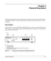
Figure 2-1 shows the front panel of the Model FE104 hub, and Figure 2-2 shows the front panel of the Model FE104 Fast Ethernet Hub Physical Description 2-1 Front panel of the Model FE108 hub. 1 2 3 4 5 Pwr Col 100BASE-TX FAST ETHERNET HUB FE104 100 Mbps F AST 1 10 20 >30 Utilization % Link/Rx Part Normal/Uplink 1 2 3 4 Key...TX port connectors, and Normal/Uplink push button. Use the key at the bottom of the Model FE104 and Model FE108 hubs. Chapter 2 Physical Description This chapter is divided into sections on each illustration to identify the associated component.
Figure 2-1 shows the front panel of the Model FE104 hub, and Figure 2-2 shows the front panel of the Model FE104 Fast Ethernet Hub Physical Description 2-1 Front panel of the Model FE108 hub. 1 2 3 4 5 Pwr Col 100BASE-TX FAST ETHERNET HUB FE104 100 Mbps F AST 1 10 20 >30 Utilization % Link/Rx Part Normal/Uplink 1 2 3 4 Key...TX port connectors, and Normal/Uplink push button. Use the key at the bottom of the Model FE104 and Model FE108 hubs. Chapter 2 Physical Description This chapter is divided into sections on each illustration to identify the associated component.

Installation Guide
Page 14
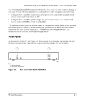
Installation Guide for the Model FE104 and Model FE108 Fast Ethernet Hubs 1 2 3 4 5 Pwr Col 100BASE-TX FAST ETHERNET HUB FE108 100 Mbps F AST 1 10 20 >30 Utilization % 1 2 3 4 Link/Rx Part Normal/Uplink 5 6 6 8 Key: 1 = Pwr (power) LED 2 = Col (collision) LED 3 = Utilization % LEDs ...segment in a standalone hub or a stack of the hub and two on the front panel of hubs • Link and receive activity for all ports in the hub • Partition status for all ports in the hub 2-2 Physical Description Front panel of the Model FE108 Fast Ethernet Hub 185EA LED Display ...
Installation Guide for the Model FE104 and Model FE108 Fast Ethernet Hubs 1 2 3 4 5 Pwr Col 100BASE-TX FAST ETHERNET HUB FE108 100 Mbps F AST 1 10 20 >30 Utilization % 1 2 3 4 Link/Rx Part Normal/Uplink 5 6 6 8 Key: 1 = Pwr (power) LED 2 = Col (collision) LED 3 = Utilization % LEDs ...segment in a standalone hub or a stack of the hub and two on the front panel of hubs • Link and receive activity for all ports in the hub • Partition status for all ports in the hub 2-2 Physical Description Front panel of the Model FE108 Fast Ethernet Hub 185EA LED Display ...

Installation Guide
Page 15
...Four LEDs indicate whether the percentage of data utilization on the front panel of the hub. Installation Guide for the Model FE104 and Model FE108 Fast Ethernet Hubs Table 2-1 describes each LED on the hub or stack of hubs is 1%, 10%, 20%, or more information on the network. The RJ-45 interface...2-1. There is an 8-pin connector. An illustration of the RJ-45 connector and a table of the Model FE104 hub provides four RJ-45 100BASE-TX ports, and the Model FE108 provides eight RJ-45 100BASE-TX ports. These standard RJ-45 connectors accept 2-pair Category 5 UTP cable or 4-pair...
...Four LEDs indicate whether the percentage of data utilization on the front panel of the hub. Installation Guide for the Model FE104 and Model FE108 Fast Ethernet Hubs Table 2-1 describes each LED on the hub or stack of hubs is 1%, 10%, 20%, or more information on the network. The RJ-45 interface...2-1. There is an 8-pin connector. An illustration of the RJ-45 connector and a table of the Model FE104 hub provides four RJ-45 100BASE-TX ports, and the Model FE108 provides eight RJ-45 100BASE-TX ports. These standard RJ-45 connectors accept 2-pair Category 5 UTP cable or 4-pair...

Installation Guide
Page 16
...FE104 Figure 2-4. Link/Rx and Part (partition) LEDs on the RJ-45 ports Normal/Uplink Push Button The Normal/Uplink push button on the Model FE108 hub. Installation Guide for the Model FE104 and Model FE108 Fast Ethernet Hubs As illustrated in , Ports 4 and 8 are configured for Port 4 on the Model FE104... hub and Port 8 on the front panel of each RJ-45 connector. When the push button is the Part (partition) LED. Both LEDs are positioned ...
...FE104 Figure 2-4. Link/Rx and Part (partition) LEDs on the RJ-45 ports Normal/Uplink Push Button The Normal/Uplink push button on the Model FE108 hub. Installation Guide for the Model FE104 and Model FE108 Fast Ethernet Hubs As illustrated in , Ports 4 and 8 are configured for Port 4 on the Model FE104... hub and Port 8 on the front panel of each RJ-45 connector. When the push button is the Part (partition) LED. Both LEDs are positioned ...
Installation Guide
Page 17
...normal port, you must use a crossover cable for daisy-chaining or cascading. Rear panel of each hub has a grounding clip and a DC power receptacle that is provided for information on the hubs cannot be configured for uplink wiring if the port is to be connected to a normal...and 8 for uplink wiring. The remaining (normal) ports on the crossover and straight-through cables). Installation Guide for the Model FE104 and Model FE108 Fast Ethernet Hubs The Normal/Uplink push button eliminates the need to use an RJ-45 crossover cable to connect the two ports (refer to Appendix C, "...
...normal port, you must use a crossover cable for daisy-chaining or cascading. Rear panel of each hub has a grounding clip and a DC power receptacle that is provided for information on the hubs cannot be configured for uplink wiring if the port is to be connected to a normal...and 8 for uplink wiring. The remaining (normal) ports on the crossover and straight-through cables). Installation Guide for the Model FE104 and Model FE108 Fast Ethernet Hubs The Normal/Uplink push button eliminates the need to use an RJ-45 crossover cable to connect the two ports (refer to Appendix C, "...
Installation Guide
Page 18
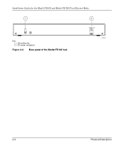
Rear panel of the Model FE108 hub 2 12 Vdc 1.2A -+ 182EA 2-6 Physical Description Installation Guide for the Model FE104 and Model FE108 Fast Ethernet Hubs 1 Key: 1 = Grounding clip 2 = DC power receptacle Figure 2-6.
Rear panel of the Model FE108 hub 2 12 Vdc 1.2A -+ 182EA 2-6 Physical Description Installation Guide for the Model FE104 and Model FE108 Fast Ethernet Hubs 1 Key: 1 = Grounding clip 2 = DC power receptacle Figure 2-6.
Installation Guide
Page 19
...F and 104° F). No nearby heat sources such as punchdown blocks or patch panels, should be complete before installing the hub. Service access Minimum 12 inches (19.68 cm) front and back for cooling. Wiring hardware Wiring hardware, such as direct sunlight... clearance for : • Preparing the site • Checking package contents • Installing a NETGEAR 100BASE-T hub • Verifying your installation Preparing the Site Before you begin installing the hub, prepare the installation site. Humidity Between 5% and 85% noncondensing. Adequate airflow in Table...
...F and 104° F). No nearby heat sources such as punchdown blocks or patch panels, should be complete before installing the hub. Service access Minimum 12 inches (19.68 cm) front and back for cooling. Wiring hardware Wiring hardware, such as direct sunlight... clearance for : • Preparing the site • Checking package contents • Installing a NETGEAR 100BASE-T hub • Verifying your installation Preparing the Site Before you begin installing the hub, prepare the installation site. Humidity Between 5% and 85% noncondensing. Adequate airflow in Table...
Installation Guide
Page 20
Keep the carton, including the original packing materials. Use them to repack the hub if you need to NETGEAR, Inc. 3-2 Installation To qualify for product updates and product warranty registrations, complete the Warranty and Owner Registration Card within 30 days ...return it to return it for repair. Installation Guide for the Model FE104 and Model FE108 Fast Ethernet Hubs Checking Package Contents This package should contain the following items: • Model FE104 or Model FE108 Fast Ethernet Hub • Rubber pads for tabletop installation • DC power adapter • Warranty ...
Keep the carton, including the original packing materials. Use them to repack the hub if you need to NETGEAR, Inc. 3-2 Installation To qualify for product updates and product warranty registrations, complete the Warranty and Owner Registration Card within 30 days ...return it to return it for repair. Installation Guide for the Model FE104 and Model FE108 Fast Ethernet Hubs Checking Package Contents This package should contain the following items: • Model FE104 or Model FE108 Fast Ethernet Hub • Rubber pads for tabletop installation • DC power adapter • Warranty ...

Installation Guide
Page 21
... the devices to the ports on a tabletop or any additional Fast Ethernet hubs in this chapter. The EIA/TIA 568-A standard recommends the installation of the hub. Installation Guide for the Model FE104 and Model FE108 Fast Ethernet Hubs Installing a NETGEAR 100BASE-TX Hub This section provides information and instructions for wiring rules and guidelines. 5. There...
... the devices to the ports on a tabletop or any additional Fast Ethernet hubs in this chapter. The EIA/TIA 568-A standard recommends the installation of the hub. Installation Guide for the Model FE104 and Model FE108 Fast Ethernet Hubs Installing a NETGEAR 100BASE-TX Hub This section provides information and instructions for wiring rules and guidelines. 5. There...

Installation Guide
Page 22
... illustrated in Normal position) 3 = PCs with information about installing multiple hubs. Daisy-chaining two Model FE108 hubs 3-4 Installation In Figure 3-2, multiple hubs are connected to "Verifying Your Installation." 1 2 Model FE108 hub Model FE108 hub 3 359EA Key: 1 = Model FE108 Fast Ethernet Hub (Normal/Uplink push button set in Uplink position) 2 = Model FE108 Fast Ethernet Hub (Normal/Uplink push button set in Figure 3-1, two...
... illustrated in Normal position) 3 = PCs with information about installing multiple hubs. Daisy-chaining two Model FE108 hubs 3-4 Installation In Figure 3-2, multiple hubs are connected to "Verifying Your Installation." 1 2 Model FE108 hub Model FE108 hub 3 359EA Key: 1 = Model FE108 Fast Ethernet Hub (Normal/Uplink push button set in Uplink position) 2 = Model FE108 Fast Ethernet Hub (Normal/Uplink push button set in Figure 3-1, two...

Installation Guide
Page 23
... push button set in Normal position) 4 = 10 Mbps connection 5 = PCs with 100 Mbps connection to Fast Ethernet hub 6 = PCs with 10 Mbps connection to Ethernet hub 7 = Model FE104 Fast Ethernet Hub (Normal/Uplink push button set in Uplink position) 8 = Model FE108 Fast Ethernet Hub (Normal/Uplink push button set in Uplink position) 9 = Model EN108 Ethernet...
... push button set in Normal position) 4 = 10 Mbps connection 5 = PCs with 100 Mbps connection to Fast Ethernet hub 6 = PCs with 10 Mbps connection to Ethernet hub 7 = Model FE104 Fast Ethernet Hub (Normal/Uplink push button set in Uplink position) 8 = Model FE108 Fast Ethernet Hub (Normal/Uplink push button set in Uplink position) 9 = Model EN108 Ethernet...

Installation Guide
Page 24
If there are any port on and shows the percentage of utilization when data is being received by any problems, refer to the hub, the following conditions should exist: • The Pwr (power) LED on the front panel is on. • The Link/Rx LED on each ... port is blinking when data is being received by that port. • The Utilization % LED on the front panel is on the hub. Installation Guide for the Model FE104 and Model FE108 Fast Ethernet Hubs Verifying Your Installation When installation is complete and power has been applied to Chapter 4, "Troubleshooting." 3-6 Installation
If there are any port on and shows the percentage of utilization when data is being received by any problems, refer to the hub, the following conditions should exist: • The Pwr (power) LED on the front panel is on. • The Link/Rx LED on each ... port is blinking when data is being received by that port. • The Utilization % LED on the front panel is on the hub. Installation Guide for the Model FE104 and Model FE108 Fast Ethernet Hubs Verifying Your Installation When installation is complete and power has been applied to Chapter 4, "Troubleshooting." 3-6 Installation

Installation Guide
Page 25
... when data is certified for 100 Mbps operation. Chapter 4 Troubleshooting This chapter provides information about troubleshooting the Model FE104 and Model FE108 hubs. Check that end. Troubleshooting 4-1 Table 4-1. It is also important that only Category 5 cable is used and that it is switched on...that there is a proper connection at that the length of the crimp on the connector is intermittent, check the port termination at hub Port connection not functioning Activity Check Pwr (power) LED off Link/Rx LED off or intermittent Check the power cord connections and ...
... when data is certified for 100 Mbps operation. Chapter 4 Troubleshooting This chapter provides information about troubleshooting the Model FE104 and Model FE108 hubs. Check that end. Troubleshooting 4-1 Table 4-1. It is also important that only Category 5 cable is used and that it is switched on...that there is a proper connection at that the length of the crimp on the connector is intermittent, check the port termination at hub Port connection not functioning Activity Check Pwr (power) LED off Link/Rx LED off or intermittent Check the power cord connections and ...
Installation Guide
Page 26
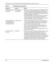
... off or intermittent Problems with Port 4 Link/Rx LED off on the Model FE104 hub or with Port 8 on the Model FE108 hub Col (collision) LED blinking Col LED on Check Make sure that the computer and hub are turned on the network. Collisions are connected on . Computers that there is installed... proper cable is power to a PC or other causes for the Model FE104 and Model FE108 Fast Ethernet Hubs Table 4-1. Try the alternate position of the Normal/Uplink push button to a router or another hub, make sure the Normal/Uplink push button is set in the PC. Excessive collisions can ...
... off or intermittent Problems with Port 4 Link/Rx LED off on the Model FE104 hub or with Port 8 on the Model FE108 hub Col (collision) LED blinking Col LED on Check Make sure that the computer and hub are turned on the network. Collisions are connected on . Computers that there is installed... proper cable is power to a PC or other causes for the Model FE104 and Model FE108 Fast Ethernet Hubs Table 4-1. Try the alternate position of the Normal/Uplink push button to a router or another hub, make sure the Normal/Uplink push button is set in the PC. Excessive collisions can ...

Installation Guide
Page 27
...Examples The Model FE104 and Model FE108 hubs are given to any 10 or 100 Mbps hub or switch. Note: When integrating a 10 Mbps and a 100 Mbps network, NETGEAR recommends that you use all devices so that they can be attached to illustrate the function of the hubs and switches in all Category 5... cabling so connections can be switched between 10 and 100 Mbps devices. NETGEAR also recommends that you use dual-speed (10/100) Ethernet adapters in several con&#...
...Examples The Model FE104 and Model FE108 hubs are given to any 10 or 100 Mbps hub or switch. Note: When integrating a 10 Mbps and a 100 Mbps network, NETGEAR recommends that you use all devices so that they can be attached to illustrate the function of the hubs and switches in all Category 5... cabling so connections can be switched between 10 and 100 Mbps devices. NETGEAR also recommends that you use dual-speed (10/100) Ethernet adapters in several con&#...
