Installation Guide
Page 2
... © 2000 by the application of EN 55 022 Class A (CISPR 22). Operation of this equipment in a residential area is not installed and used in which case users will be required to take appropriate measures. All rights reserved. Warning: This is a registered trademark of improving ... in a commercial environment. Bestätigung des Herstellers/Importeurs Es wird hiermit bestätigt, daß das NETGEAR Model FE104 and Model FE108 Fast Ethernet Hubs gemäß der im BMPT-AmtsblVfg 243/1991 und Vfg 46/1992 aufgeführten Bestimmungen entstört ist...
... © 2000 by the application of EN 55 022 Class A (CISPR 22). Operation of this equipment in a residential area is not installed and used in which case users will be required to take appropriate measures. All rights reserved. Warning: This is a registered trademark of improving ... in a commercial environment. Bestätigung des Herstellers/Importeurs Es wird hiermit bestätigt, daß das NETGEAR Model FE104 and Model FE108 Fast Ethernet Hubs gemäß der im BMPT-AmtsblVfg 243/1991 und Vfg 46/1992 aufgeführten Bestimmungen entstört ist...
Installation Guide
Page 3
... to the Internet and a Web browser such as radios and TV receivers. Customer Support For assistance with installing and configuring your NETGEAR system or with post-installation questions or problems, contact your point of this equipment is in the first category (information equipment ...and/or industrial areas. To contact customer support or to the standards set by the Voluntary Control Council for other NETGEAR products, you can contact NETGEAR at the following numbers: Phone: Australia Austria Denmark Canada Finland France Germany Hong Kong Japan 1800-787-638 00800-...
... to the Internet and a Web browser such as radios and TV receivers. Customer Support For assistance with installing and configuring your NETGEAR system or with post-installation questions or problems, contact your point of this equipment is in the first category (information equipment ...and/or industrial areas. To contact customer support or to the standards set by the Voluntary Control Council for other NETGEAR products, you can contact NETGEAR at the following numbers: Phone: Australia Austria Denmark Canada Finland France Germany Hong Kong Japan 1800-787-638 00800-...
Installation Guide
Page 5
... Panel ...2-1 LED Display ...2-2 RJ-45 100BASE-TX Ports 2-3 Normal/Uplink Push Button 2-4 Rear Panel ...2-5 Chapter 3 Installation Preparing the Site ...3-1 Checking Package Contents 3-2 Installing a NETGEAR 100BASE-TX Hub 3-3 Installing the Hub on a Flat Surface 3-3 Installing Multiple Hubs 3-4 Verifying Your Installation 3-6 Chapter 4 Troubleshooting Troubleshooting the Hub and the Network 4-1 Chapter 5 Network Configuration Configuration Examples 5-1 100BASE-TX Shared Repeater...
... Panel ...2-1 LED Display ...2-2 RJ-45 100BASE-TX Ports 2-3 Normal/Uplink Push Button 2-4 Rear Panel ...2-5 Chapter 3 Installation Preparing the Site ...3-1 Checking Package Contents 3-2 Installing a NETGEAR 100BASE-TX Hub 3-3 Installing the Hub on a Flat Surface 3-3 Installing Multiple Hubs 3-4 Verifying Your Installation 3-6 Chapter 4 Troubleshooting Troubleshooting the Hub and the Network 4-1 Chapter 5 Network Configuration Configuration Examples 5-1 100BASE-TX Shared Repeater...
Installation Guide
Page 11
...Mbps. This guide is intended for connecting multiple hubs, connecting Fast Ethernet stations, and making network connections. By installing the Model FE104 or Model FE108 hub in your purchase of basic Ethernet • ...FE104 4-port Fast Ethernet Hub or the NETGEAR Model FE108 8-port Fast Ethernet Hub. Users who can increase the bandwidth and improve response times. This guide describes how to a 100 Mbps network, you can create a power workgroup with the differences between the 10BASE-T and 100BASE-T specifications Introduction 1-1 By migrating these users to install...
...Mbps. This guide is intended for connecting multiple hubs, connecting Fast Ethernet stations, and making network connections. By installing the Model FE104 or Model FE108 hub in your purchase of basic Ethernet • ...FE104 4-port Fast Ethernet Hub or the NETGEAR Model FE108 8-port Fast Ethernet Hub. Users who can increase the bandwidth and improve response times. This guide describes how to a 100 Mbps network, you can create a power workgroup with the differences between the 10BASE-T and 100BASE-T specifications Introduction 1-1 By migrating these users to install...

Installation Guide
Page 12
Installation Guide for the Model FE104 and Model FE108 Fast Ethernet Hubs Features The Model FE104 and Model FE108 hubs have the following key features: • IEEE 802.3u standard compliance allows interoperation with all 100BASE-TX Fast Ethernet (100 Mbps) products. • Class II compliance enables network expansion by daisy-chaining two hubs together. • Easy...
Installation Guide for the Model FE104 and Model FE108 Fast Ethernet Hubs Features The Model FE104 and Model FE108 hubs have the following key features: • IEEE 802.3u standard compliance allows interoperation with all 100BASE-TX Fast Ethernet (100 Mbps) products. • Class II compliance enables network expansion by daisy-chaining two hubs together. • Easy...

Installation Guide
Page 14
Installation Guide for all ports in the hub 2-2 Physical Description Front panel of the Model FE108 Fast Ethernet Hub 185EA LED Display Three LEDs on the front panel of the hub and two on each port connector allow you to identify the following information: • Status of the hub...utilization percentage of the Ethernet segment in a standalone hub or a stack of hubs • Link and receive activity for all ports in the hub • Partition status for the Model FE104 and Model FE108 Fast Ethernet Hubs 1 2 3 4 5 Pwr Col 100BASE-TX FAST ETHERNET HUB FE108 100 Mbps F AST 1 10 20 >...
Installation Guide for all ports in the hub 2-2 Physical Description Front panel of the Model FE108 Fast Ethernet Hub 185EA LED Display Three LEDs on the front panel of the hub and two on each port connector allow you to identify the following information: • Status of the hub...utilization percentage of the Ethernet segment in a standalone hub or a stack of hubs • Link and receive activity for all ports in the hub • Partition status for the Model FE104 and Model FE108 Fast Ethernet Hubs 1 2 3 4 5 Pwr Col 100BASE-TX FAST ETHERNET HUB FE108 100 Mbps F AST 1 10 20 >...

Installation Guide
Page 15
... Appendix B, "RJ-45 Connector Information." Four LEDs indicate whether the percentage of data utilization on the hub or stack of excessive collisions or jabber conditions. The port is an 8-pin connector. Table B-1 provides...-TX networks require only 2-pair wiring). Caution: 100 Mbps operation requires the use of the Model FE104 hub provides four RJ-45 100BASE-TX ports, and the Model FE108 provides eight RJ-45 100BASE-TX ... normal. There is good. Refer to the hub. Installation Guide for the Model FE104 and Model FE108 Fast Ethernet Hubs Table 2-1 describes each LED on cabling.
... Appendix B, "RJ-45 Connector Information." Four LEDs indicate whether the percentage of data utilization on the hub or stack of excessive collisions or jabber conditions. The port is an 8-pin connector. Table B-1 provides...-TX networks require only 2-pair wiring). Caution: 100 Mbps operation requires the use of the Model FE104 hub provides four RJ-45 100BASE-TX ports, and the Model FE108 provides eight RJ-45 100BASE-TX ... normal. There is good. Refer to the hub. Installation Guide for the Model FE104 and Model FE108 Fast Ethernet Hubs Table 2-1 describes each LED on cabling.

Installation Guide
Page 16
Installation Guide for the Model FE104 and Model FE108 Fast Ethernet Hubs As illustrated in Figure 2-3, two LEDs are positioned at the top corners of the hub, as illustrated in Figure 2-4, allows you to select uplink (MDI) or normal (MDI-X) wiring for Port 4 on the Model FE104 hub and Port 8 on the front panel...Description Link/Rx and Part (partition) LEDs on the RJ-45 ports Normal/Uplink Push Button The Normal/Uplink push button on the Model FE108 hub. When the push button is pressed in, Ports 4 and 8 are configured for uplink wiring. Link/Rx Part MODELFE104 Normal/Uplink ...
Installation Guide for the Model FE104 and Model FE108 Fast Ethernet Hubs As illustrated in Figure 2-3, two LEDs are positioned at the top corners of the hub, as illustrated in Figure 2-4, allows you to select uplink (MDI) or normal (MDI-X) wiring for Port 4 on the Model FE104 hub and Port 8 on the front panel...Description Link/Rx and Part (partition) LEDs on the RJ-45 ports Normal/Uplink Push Button The Normal/Uplink push button on the Model FE108 hub. When the push button is pressed in, Ports 4 and 8 are configured for uplink wiring. Link/Rx Part MODELFE104 Normal/Uplink ...
Installation Guide
Page 17
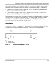
...for daisy-chaining or cascading. Rear Panel As illustrated in Figure 2-5 and Figure 2-6, the rear panel of the Model FE104 hub 196EA Physical Description 2-5 Rear panel of each hub has a grounding clip and a DC power receptacle that is to be connected to Appendix C, "Fast Ethernet and Cabling ... port, you are using one of these ports to connect to another hub. The remaining (normal) ports on the crossover and straight-through cables). Installation Guide for the Model FE104 and Model FE108 Fast Ethernet Hubs The Normal/Uplink push button eliminates the need to the supplied DC power...
...for daisy-chaining or cascading. Rear Panel As illustrated in Figure 2-5 and Figure 2-6, the rear panel of the Model FE104 hub 196EA Physical Description 2-5 Rear panel of each hub has a grounding clip and a DC power receptacle that is to be connected to Appendix C, "Fast Ethernet and Cabling ... port, you are using one of these ports to connect to another hub. The remaining (normal) ports on the crossover and straight-through cables). Installation Guide for the Model FE104 and Model FE108 Fast Ethernet Hubs The Normal/Uplink push button eliminates the need to the supplied DC power...
Installation Guide
Page 18
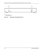
Installation Guide for the Model FE104 and Model FE108 Fast Ethernet Hubs 1 Key: 1 = Grounding clip 2 = DC power receptacle Figure 2-6. Rear panel of the Model FE108 hub 2 12 Vdc 1.2A -+ 182EA 2-6 Physical Description
Installation Guide for the Model FE104 and Model FE108 Fast Ethernet Hubs 1 Key: 1 = Grounding clip 2 = DC power receptacle Figure 2-6. Rear panel of the Model FE108 hub 2 12 Vdc 1.2A -+ 182EA 2-6 Physical Description
Installation Guide
Page 19
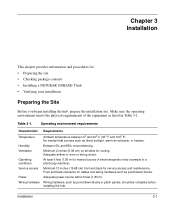
...64258;ow in Table 3-1. No nearby heat sources such as punchdown blocks or patch panels, should be complete before installing the hub. Power Adequate power source within 6 feet (1.83 m). Operating environment requirements Characteristic Requirements Temperature Ambient temperature between 0°... : • Preparing the site • Checking package contents • Installing a NETGEAR 100BASE-T hub • Verifying your installation Preparing the Site Before you begin installing the hub, prepare the installation site. Ventilation Minimum 2 inches (5.08 cm) on all sides for cables...
...64258;ow in Table 3-1. No nearby heat sources such as punchdown blocks or patch panels, should be complete before installing the hub. Power Adequate power source within 6 feet (1.83 m). Operating environment requirements Characteristic Requirements Temperature Ambient temperature between 0°... : • Preparing the site • Checking package contents • Installing a NETGEAR 100BASE-T hub • Verifying your installation Preparing the Site Before you begin installing the hub, prepare the installation site. Ventilation Minimum 2 inches (5.08 cm) on all sides for cables...
Installation Guide
Page 20
... FE104 or Model FE108 Fast Ethernet Hub • Rubber pads for tabletop installation • DC power adapter • Warranty and Owner Registration Card • This manual Call your reseller or customer support in your area if there are any wrong, missing, or damaged parts. Refer to NETGEAR, Inc. 3-2 Installation Use... them to repack the hub if you need to return it to page iii for the location of purchase and return it for product updates...
... FE104 or Model FE108 Fast Ethernet Hub • Rubber pads for tabletop installation • DC power adapter • Warranty and Owner Registration Card • This manual Call your reseller or customer support in your area if there are any wrong, missing, or damaged parts. Refer to NETGEAR, Inc. 3-2 Installation Use... them to repack the hub if you need to return it to page iii for the location of purchase and return it for product updates...

Installation Guide
Page 21
...;rst and then connect the power adapter to follow these steps: 1. Installation Guide for the Model FE104 and Model FE108 Fast Ethernet Hubs Installing a NETGEAR 100BASE-TX Hub This section provides information and instructions for installing the hub on a tabletop or any additional Fast Ethernet hubs in your cables perform to Appendix C, "Fast Ethernet and Cabling Guidelines," for wiring...
...;rst and then connect the power adapter to follow these steps: 1. Installation Guide for the Model FE104 and Model FE108 Fast Ethernet Hubs Installing a NETGEAR 100BASE-TX Hub This section provides information and instructions for installing the hub on a tabletop or any additional Fast Ethernet hubs in your cables perform to Appendix C, "Fast Ethernet and Cabling Guidelines," for wiring...

Installation Guide
Page 22
Daisy-chaining two Model FE108 hubs 3-4 Installation Installation Guide for the Model FE104 and Model FE108 Fast Ethernet Hubs Installing Multiple Hubs This section provides you have installed your hubs using one of the methods shown, connect the power adapter to the wall, and proceed to a server through the Model FS104 10/100 Mbps Fast ...
Daisy-chaining two Model FE108 hubs 3-4 Installation Installation Guide for the Model FE104 and Model FE108 Fast Ethernet Hubs Installing Multiple Hubs This section provides you have installed your hubs using one of the methods shown, connect the power adapter to the wall, and proceed to a server through the Model FS104 10/100 Mbps Fast ...

Installation Guide
Page 23
Connecting multiple hubs Installation 3-5 Installation Guide for the Model FE104 and Model FE108 Fast Ethernet Hubs 1 23 4 Model FS104 switch Model FE104 hub Model FE108 hub 5 Model EN108 hub 5 6 7 8 9 199EA Key: 1 = 100 Mbps connection 2 = Server 3 = FS104 10/100 Mbps switch (Normal/Uplink push button set in Normal position) 4 = 10 Mbps connection 5 = PCs with 100 Mbps connection to Fast Ethernet hub 6 = PCs...
Connecting multiple hubs Installation 3-5 Installation Guide for the Model FE104 and Model FE108 Fast Ethernet Hubs 1 23 4 Model FS104 switch Model FE104 hub Model FE108 hub 5 Model EN108 hub 5 6 7 8 9 199EA Key: 1 = 100 Mbps connection 2 = Server 3 = FS104 10/100 Mbps switch (Normal/Uplink push button set in Normal position) 4 = 10 Mbps connection 5 = PCs with 100 Mbps connection to Fast Ethernet hub 6 = PCs...

Installation Guide
Page 24
... of utilization when data is being received by any problems, refer to Chapter 4, "Troubleshooting." 3-6 Installation Installation Guide for the Model FE104 and Model FE108 Fast Ethernet Hubs Verifying Your Installation When installation is complete and power has been applied to the hub, the following conditions should exist: • The Pwr (power) LED on the front panel is... on the connected port is blinking when data is being received by that port. • The Utilization % LED on the front panel is on the hub.
... of utilization when data is being received by any problems, refer to Chapter 4, "Troubleshooting." 3-6 Installation Installation Guide for the Model FE104 and Model FE108 Fast Ethernet Hubs Verifying Your Installation When installation is complete and power has been applied to the hub, the following conditions should exist: • The Pwr (power) LED on the front panel is... on the connected port is blinking when data is being received by that port. • The Utilization % LED on the front panel is on the hub.
Installation Guide
Page 26
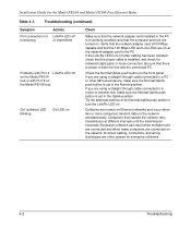
... button is installed, and check for the Model FE104 and Model FE108 Fast Ethernet Hubs Table 4-1. Troubleshooting (continued) Symptom Port connection not functioning Activity Link/Rx LED off or intermittent Problems with Port 4 Link/Rx LED off on the Model FE104 hub or with Port 8 on the Model FE108 hub Col (collision...) LED blinking Col LED on Check Make sure that the network adapter card installed in the PC is in working condition and that the proper cable ...
... button is installed, and check for the Model FE104 and Model FE108 Fast Ethernet Hubs Table 4-1. Troubleshooting (continued) Symptom Port connection not functioning Activity Link/Rx LED off or intermittent Problems with Port 4 Link/Rx LED off on the Model FE104 hub or with Port 8 on the Model FE108 hub Col (collision...) LED blinking Col LED on Check Make sure that the network adapter card installed in the PC is in working condition and that the proper cable ...

Installation Guide
Page 28
... network and provides transparent communication among 10 Mbps users and 100 Mbps users. 5-2 Network Configuration Installation Guide for the Model FE104 and Model FE108 Fast Ethernet Hubs 100BASE-TX Shared Repeater In the configuration for 100BASE-TX shared repeaters, the Model...NETGEAR Model SW502 Ethernet Switch that has one 10 Mbps port and one server on the Model SW502 switch. As illustrated in Normal position on both hubs) 4 = Server 188EA Figure 5-1. In many users are used in a standalone network with users attached directly to the hub. 12 3 Model FE104 hub...
... network and provides transparent communication among 10 Mbps users and 100 Mbps users. 5-2 Network Configuration Installation Guide for the Model FE104 and Model FE108 Fast Ethernet Hubs 100BASE-TX Shared Repeater In the configuration for 100BASE-TX shared repeaters, the Model...NETGEAR Model SW502 Ethernet Switch that has one 10 Mbps port and one server on the Model SW502 switch. As illustrated in Normal position on both hubs) 4 = Server 188EA Figure 5-1. In many users are used in a standalone network with users attached directly to the hub. 12 3 Model FE104 hub...

Installation Guide
Page 29
... on port connected to 100 Mbps Network Configuration 5-3 Installation Guide for the Model FE104 and Model FE108 Fast Ethernet Hubs 7 12 3 Model FE104 hub 4 56 Model SW502 switch 1 2 Model EN516 hub Model EN516 hub Model EN516 hub 8 8 7 7 217EA Key: 1 = PCs with 100 Mbps connections 2 = 100 Mbps connection 3 = Model FE104 Fast Ethernet Hub (Normal/Uplink push button set in Normal position...
... on port connected to 100 Mbps Network Configuration 5-3 Installation Guide for the Model FE104 and Model FE108 Fast Ethernet Hubs 7 12 3 Model FE104 hub 4 56 Model SW502 switch 1 2 Model EN516 hub Model EN516 hub Model EN516 hub 8 8 7 7 217EA Key: 1 = PCs with 100 Mbps connections 2 = 100 Mbps connection 3 = Model FE104 Fast Ethernet Hub (Normal/Uplink push button set in Normal position...

Installation Guide
Page 30
...fic from one 10 Mbps segment passes to segment the 10 Mbps traffic on the hubs. Installation Guide for the Model FE104 and Model FE108 Fast Ethernet Hubs Multiport Switch with Fast Ethernet Backbone If the 10 Mbps shared repeater portion of the network experiences ...segment only when addressing a node on one 100 Mbps port to the other segments. 12 3 4 56 Model FE108 hub Model SW507 switch Model EN516 hub Model EN516 hub Model EN516 hub 7 7 7 216EA Key: 1 = PCs with Fast Ethernet backbone 5-4 Network Configuration As illustrated in Uplink position) Figure 5-3....
...fic from one 10 Mbps segment passes to segment the 10 Mbps traffic on the hubs. Installation Guide for the Model FE104 and Model FE108 Fast Ethernet Hubs Multiport Switch with Fast Ethernet Backbone If the 10 Mbps shared repeater portion of the network experiences ...segment only when addressing a node on one 100 Mbps port to the other segments. 12 3 4 56 Model FE108 hub Model SW507 switch Model EN516 hub Model EN516 hub Model EN516 hub 7 7 7 216EA Key: 1 = PCs with Fast Ethernet backbone 5-4 Network Configuration As illustrated in Uplink position) Figure 5-3....


