Installation Guide
Page 2
...the use or application of the product(s) or circuit layout(s) described herein. These limits are shielded against harmful interference when the equipment is not installed and used in a commercial environment. © 2000 by the application of EN 55 022 Class A (CISPR 22). All rights reserved. Information... is a Class A product. Bestätigung des Herstellers/Importeurs Es wird hiermit bestätigt, daß das NETGEAR Model FE104 and Model FE108 Fast Ethernet Hubs gemäß der im BMPT-AmtsblVfg 243/1991 und Vfg 46/1992 aufgeführten Bestimmungen entstört ist....
...the use or application of the product(s) or circuit layout(s) described herein. These limits are shielded against harmful interference when the equipment is not installed and used in a commercial environment. © 2000 by the application of EN 55 022 Class A (CISPR 22). All rights reserved. Information... is a Class A product. Bestätigung des Herstellers/Importeurs Es wird hiermit bestätigt, daß das NETGEAR Model FE104 and Model FE108 Fast Ethernet Hubs gemäß der im BMPT-AmtsblVfg 243/1991 und Vfg 46/1992 aufgeführten Bestimmungen entstört ist....
Installation Guide
Page 3
...-4566 0200-298-298 00800-0638-4327 (00800-0-NETGEAR) 020-7216-0014 1-888-NETGEAR +1 801-236-8499 World Wide Web NETGEAR maintains a World Wide Web Home Page that are required. iii Customer Support For assistance with installing and configuring your NETGEAR system or with post-installation questions or problems, contact your point of this...
...-4566 0200-298-298 00800-0638-4327 (00800-0-NETGEAR) 020-7216-0014 1-888-NETGEAR +1 801-236-8499 World Wide Web NETGEAR maintains a World Wide Web Home Page that are required. iii Customer Support For assistance with installing and configuring your NETGEAR system or with post-installation questions or problems, contact your point of this...
Installation Guide
Page 5
... Panel ...2-1 LED Display ...2-2 RJ-45 100BASE-TX Ports 2-3 Normal/Uplink Push Button 2-4 Rear Panel ...2-5 Chapter 3 Installation Preparing the Site ...3-1 Checking Package Contents 3-2 Installing a NETGEAR 100BASE-TX Hub 3-3 Installing the Hub on a Flat Surface 3-3 Installing Multiple Hubs 3-4 Verifying Your Installation 3-6 Chapter 4 Troubleshooting Troubleshooting the Hub and the Network 4-1 Chapter 5 Network Configuration Configuration Examples 5-1 100BASE-TX Shared Repeater...
... Panel ...2-1 LED Display ...2-2 RJ-45 100BASE-TX Ports 2-3 Normal/Uplink Push Button 2-4 Rear Panel ...2-5 Chapter 3 Installation Preparing the Site ...3-1 Checking Package Contents 3-2 Installing a NETGEAR 100BASE-TX Hub 3-3 Installing the Hub on a Flat Surface 3-3 Installing Multiple Hubs 3-4 Verifying Your Installation 3-6 Chapter 4 Troubleshooting Troubleshooting the Hub and the Network 4-1 Chapter 5 Network Configuration Configuration Examples 5-1 100BASE-TX Shared Repeater...
Installation Guide
Page 11
...making network connections. Users who have the following background and experience: • Working knowledge of the NETGEAR™ Model FE104 4-port Fast Ethernet Hub or the NETGEAR Model FE108 8-port Fast Ethernet Hub. Chapter 1 Introduction Congratulations on powerful workstations require more bandwidth than the conventional 10BASE-T network. By ... you can share access to centralized network devices (such as servers and printers) at 100 Mbps. Both hubs are designed to install and use the hubs. This guide describes how to support power workgroups operating at 100 Mbps.
...making network connections. Users who have the following background and experience: • Working knowledge of the NETGEAR™ Model FE104 4-port Fast Ethernet Hub or the NETGEAR Model FE108 8-port Fast Ethernet Hub. Chapter 1 Introduction Congratulations on powerful workstations require more bandwidth than the conventional 10BASE-T network. By ... you can share access to centralized network devices (such as servers and printers) at 100 Mbps. Both hubs are designed to install and use the hubs. This guide describes how to support power workgroups operating at 100 Mbps.

Installation Guide
Page 12
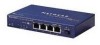
...; Compact, sturdy metal case design enables easy tabletop or under-desk installation. 1-2 Introduction Normal/Uplink push button to clearly indicate the status of each port. - Installation Guide for the Model FE104 and Model FE108 Fast Ethernet Hubs Features The Model FE104 and Model FE108 hubs have the following key features: • IEEE 802.3u standard compliance...
...; Compact, sturdy metal case design enables easy tabletop or under-desk installation. 1-2 Introduction Normal/Uplink push button to clearly indicate the status of each port. - Installation Guide for the Model FE104 and Model FE108 Fast Ethernet Hubs Features The Model FE104 and Model FE108 hubs have the following key features: • IEEE 802.3u standard compliance...

Installation Guide
Page 14
... percentage of the Ethernet segment in a standalone hub or a stack of hubs • Link and receive activity for all ports in the hub • Partition status for the Model FE104 and Model FE108 Fast Ethernet Hubs 1 2 3 4 5 Pwr Col 100BASE-TX FAST ETHERNET HUB FE108 100 Mbps F AST 1 10 20... >30 Utilization % 1 2 3 4 Link/Rx Part Normal/Uplink 5 6 6 8 Key: 1 = Pwr (power) LED 2 = Col (collision) LED 3 = Utilization % LEDs 4 = RJ-45 ports with Link/Rx and Part (partition) LEDs on each port 5 = Normal/Uplink push button Figure 2-2. Installation...
... percentage of the Ethernet segment in a standalone hub or a stack of hubs • Link and receive activity for all ports in the hub • Partition status for the Model FE104 and Model FE108 Fast Ethernet Hubs 1 2 3 4 5 Pwr Col 100BASE-TX FAST ETHERNET HUB FE108 100 Mbps F AST 1 10 20... >30 Utilization % 1 2 3 4 Link/Rx Part Normal/Uplink 5 6 6 8 Key: 1 = Pwr (power) LED 2 = Col (collision) LED 3 = Utilization % LEDs 4 = RJ-45 ports with Link/Rx and Part (partition) LEDs on each port 5 = Normal/Uplink push button Figure 2-2. Installation...

Installation Guide
Page 15
...partitioned because of hubs is supplied to Appendix C, "Fast Ethernet and Cabling Guidelines," for the normal (MDI-X) RJ-45 connector and the uplink (MDI) RJ-45 connector are normal. An illustration of the RJ-45 connector and a table of the hub. Installation Guide for the Model FE104 and Model FE108... Fast Ethernet Hubs Table 2-1 describes each LED on the front panel of pin assignments for more than 30%. These standard RJ-45...
...partitioned because of hubs is supplied to Appendix C, "Fast Ethernet and Cabling Guidelines," for the normal (MDI-X) RJ-45 connector and the uplink (MDI) RJ-45 connector are normal. An illustration of the RJ-45 connector and a table of the hub. Installation Guide for the Model FE104 and Model FE108... Fast Ethernet Hubs Table 2-1 describes each LED on the front panel of pin assignments for more than 30%. These standard RJ-45...

Installation Guide
Page 16
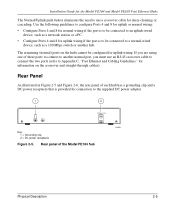
... is in , Ports 4 and 8 are configured for Port 4 on the Model FE104 hub and Port 8 on the front panel of each RJ-45 connector. Installation Guide for the Model FE104 and Model FE108 Fast Ethernet Hubs As illustrated in Figure 2-3, two LEDs are positioned at the top corners of the... hub, as illustrated in Figure 2-4, allows you to select uplink (MDI) or normal (MDI-X) wiring...
... is in , Ports 4 and 8 are configured for Port 4 on the Model FE104 hub and Port 8 on the front panel of each RJ-45 connector. Installation Guide for the Model FE104 and Model FE108 Fast Ethernet Hubs As illustrated in Figure 2-3, two LEDs are positioned at the top corners of the... hub, as illustrated in Figure 2-4, allows you to select uplink (MDI) or normal (MDI-X) wiring...
Installation Guide
Page 17
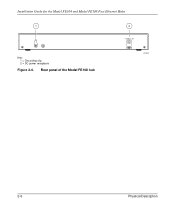
Installation Guide for the Model FE104 and Model FE108 Fast Ethernet Hubs The Normal/Uplink push button eliminates the need to use an RJ-45 crossover cable to connect the two ports (refer to Appendix C, "Fast Ethernet and Cabling Guidelines," for information on the hubs cannot be connected to... on the crossover and straight-through cables). If you must use a crossover cable for daisy-chaining or cascading. Rear panel of the Model FE104 hub 196EA Physical Description 2-5 Use the following guidelines to configure Ports 4 and 8 for uplink or normal wiring: • Confi...
Installation Guide for the Model FE104 and Model FE108 Fast Ethernet Hubs The Normal/Uplink push button eliminates the need to use an RJ-45 crossover cable to connect the two ports (refer to Appendix C, "Fast Ethernet and Cabling Guidelines," for information on the hubs cannot be connected to... on the crossover and straight-through cables). If you must use a crossover cable for daisy-chaining or cascading. Rear panel of the Model FE104 hub 196EA Physical Description 2-5 Use the following guidelines to configure Ports 4 and 8 for uplink or normal wiring: • Confi...
Installation Guide
Page 18
Installation Guide for the Model FE104 and Model FE108 Fast Ethernet Hubs 1 Key: 1 = Grounding clip 2 = DC power receptacle Figure 2-6. Rear panel of the Model FE108 hub 2 12 Vdc 1.2A -+ 182EA 2-6 Physical Description
Installation Guide for the Model FE104 and Model FE108 Fast Ethernet Hubs 1 Key: 1 = Grounding clip 2 = DC power receptacle Figure 2-6. Rear panel of the Model FE108 hub 2 12 Vdc 1.2A -+ 182EA 2-6 Physical Description
Installation Guide
Page 19
... Front and back clearance for : • Preparing the site • Checking package contents • Installing a NETGEAR 100BASE-T hub • Verifying your installation Preparing the Site Before you begin installing the hub, prepare the installation site. Installation 3-1 No nearby heat sources such as punchdown blocks or patch panels, should be complete before... installing the hub. Power Adequate power source within 6 feet (1.83 m). Operating conditions At least 6 feet (1.83 m) to nearest source of...
... Front and back clearance for : • Preparing the site • Checking package contents • Installing a NETGEAR 100BASE-T hub • Verifying your installation Preparing the Site Before you begin installing the hub, prepare the installation site. Installation 3-1 No nearby heat sources such as punchdown blocks or patch panels, should be complete before... installing the hub. Power Adequate power source within 6 feet (1.83 m). Operating conditions At least 6 feet (1.83 m) to nearest source of...
Installation Guide
Page 20
Refer to NETGEAR, Inc. 3-2 Installation To qualify for product updates and product warranty registrations, complete the Warranty and Owner Registration Card within 30 days of customer support in your area. Use them to repack the hub if you need to return it to ..., including the original packing materials. Installation Guide for the Model FE104 and Model FE108 Fast Ethernet Hubs Checking Package Contents This package should contain the following items: • Model FE104 or Model FE108 Fast Ethernet Hub • Rubber pads for tabletop installation • DC power adapter •...
Refer to NETGEAR, Inc. 3-2 Installation To qualify for product updates and product warranty registrations, complete the Warranty and Owner Registration Card within 30 days of customer support in your area. Use them to repack the hub if you need to return it to ..., including the original packing materials. Installation Guide for the Model FE104 and Model FE108 Fast Ethernet Hubs Checking Package Contents This package should contain the following items: • Model FE104 or Model FE108 Fast Ethernet Hub • Rubber pads for tabletop installation • DC power adapter •...

Installation Guide
Page 21
... Cabling Guidelines," to follow these steps: 1. Installation Guide for the Model FE104 and Model FE108 Fast Ethernet Hubs Installing a NETGEAR 100BASE-TX Hub This section provides information and instructions for wiring rules and guidelines. 5. Connect the devices to the ports on the hub using Category 5 UTP cable and connectors to "Installing Multiple Hubs." 4. Use the guidelines outlined in this...
... Cabling Guidelines," to follow these steps: 1. Installation Guide for the Model FE104 and Model FE108 Fast Ethernet Hubs Installing a NETGEAR 100BASE-TX Hub This section provides information and instructions for wiring rules and guidelines. 5. Connect the devices to the ports on the hub using Category 5 UTP cable and connectors to "Installing Multiple Hubs." 4. Use the guidelines outlined in this...

Installation Guide
Page 22
After you with 100 Mbps connection Figure 3-1. Daisy-chaining two Model FE108 hubs 3-4 Installation Installation Guide for the Model FE104 and Model FE108 Fast Ethernet Hubs Installing Multiple Hubs This section provides you have installed your hubs using one of the methods shown, connect the power adapter to the wall, and proceed to a server through the Model FS104 10/100...
After you with 100 Mbps connection Figure 3-1. Daisy-chaining two Model FE108 hubs 3-4 Installation Installation Guide for the Model FE104 and Model FE108 Fast Ethernet Hubs Installing Multiple Hubs This section provides you have installed your hubs using one of the methods shown, connect the power adapter to the wall, and proceed to a server through the Model FS104 10/100...

Installation Guide
Page 23
Connecting multiple hubs Installation 3-5 Installation Guide for the Model FE104 and Model FE108 Fast Ethernet Hubs 1 23 4 Model FS104 switch Model FE104 hub Model FE108 hub 5 Model EN108 hub 5 6 7 8 9 199EA Key: 1 = 100 Mbps connection 2 = Server 3 = FS104 10/100 Mbps switch (Normal/Uplink push button set in Normal position) 4 = 10 Mbps connection 5 = PCs with 100 Mbps connection to Fast Ethernet hub 6 = PCs...
Connecting multiple hubs Installation 3-5 Installation Guide for the Model FE104 and Model FE108 Fast Ethernet Hubs 1 23 4 Model FS104 switch Model FE104 hub Model FE108 hub 5 Model EN108 hub 5 6 7 8 9 199EA Key: 1 = 100 Mbps connection 2 = Server 3 = FS104 10/100 Mbps switch (Normal/Uplink push button set in Normal position) 4 = 10 Mbps connection 5 = PCs with 100 Mbps connection to Fast Ethernet hub 6 = PCs...

Installation Guide
Page 24
... the Model FE104 and Model FE108 Fast Ethernet Hubs Verifying Your Installation When installation is complete and power has been applied to Chapter 4, "Troubleshooting." 3-6 Installation If there are any port on and shows the percentage of utilization when data is being received by any problems, refer to the hub, the following conditions should exist: • The... on the connected port is blinking when data is being received by that port. • The Utilization % LED on the front panel is on the hub.
... the Model FE104 and Model FE108 Fast Ethernet Hubs Verifying Your Installation When installation is complete and power has been applied to Chapter 4, "Troubleshooting." 3-6 Installation If there are any port on and shows the percentage of utilization when data is being received by any problems, refer to the hub, the following conditions should exist: • The... on the connected port is blinking when data is being received by that port. • The Utilization % LED on the front panel is on the hub.
Installation Guide
Page 26
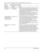
... not functioning Activity Link/Rx LED off or intermittent Problems with Port 4 Link/Rx LED off on the Model FE104 hub or with Port 8 on the Model FE108 hub Col (collision) LED blinking Col LED on . If you are normal on Ethernet networks and occur when two or...push button on . Try the alternate position of the Normal/Uplink push button to a PC or other causes for the Model FE104 and Model FE108 Fast Ethernet Hubs Table 4-1. Installation Guide for excessive collisions. 4-2 Troubleshooting Verify that the network adapter card is100 Mbps capable and that the computer and...
... not functioning Activity Link/Rx LED off or intermittent Problems with Port 4 Link/Rx LED off on the Model FE104 hub or with Port 8 on the Model FE108 hub Col (collision) LED blinking Col LED on . If you are normal on Ethernet networks and occur when two or...push button on . Try the alternate position of the Normal/Uplink push button to a PC or other causes for the Model FE104 and Model FE108 Fast Ethernet Hubs Table 4-1. Installation Guide for excessive collisions. 4-2 Troubleshooting Verify that the network adapter card is100 Mbps capable and that the computer and...

Installation Guide
Page 28
...NETGEAR Model SW502 Ethernet Switch that has one 10 Mbps port and one server on a 10 Mbps link, congestion and collisions may occur more common problems affecting network performance is access to be used in Normal position on both hubs) 4 = Server 188EA Figure 5-1. Installation Guide for the Model FE104... and Model FE108 Fast Ethernet Hubs 100BASE-TX Shared Repeater In the configuration for 100BASE-TX shared ...
...NETGEAR Model SW502 Ethernet Switch that has one 10 Mbps port and one server on a 10 Mbps link, congestion and collisions may occur more common problems affecting network performance is access to be used in Normal position on both hubs) 4 = Server 188EA Figure 5-1. Installation Guide for the Model FE104... and Model FE108 Fast Ethernet Hubs 100BASE-TX Shared Repeater In the configuration for 100BASE-TX shared ...

Installation Guide
Page 29
... Uplink position) 8 = PCs with 10 Mbps connections Figure 5-2. Installation Guide for the Model FE104 and Model FE108 Fast Ethernet Hubs 7 12 3 Model FE104 hub 4 56 Model SW502 switch 1 2 Model EN516 hub Model EN516 hub Model EN516 hub 8 8 7 7 217EA Key: 1 = PCs with 100 Mbps connections 2 = 100 Mbps connection 3 = Model FE104 Fast Ethernet Hub (Normal/Uplink push button set in Normal position...
... Uplink position) 8 = PCs with 10 Mbps connections Figure 5-2. Installation Guide for the Model FE104 and Model FE108 Fast Ethernet Hubs 7 12 3 Model FE104 hub 4 56 Model SW502 switch 1 2 Model EN516 hub Model EN516 hub Model EN516 hub 8 8 7 7 217EA Key: 1 = PCs with 100 Mbps connections 2 = 100 Mbps connection 3 = Model FE104 Fast Ethernet Hub (Normal/Uplink push button set in Normal position...

Installation Guide
Page 30
... passes to the other segments. 12 3 4 56 Model FE108 hub Model SW507 switch Model EN516 hub Model EN516 hub Model EN516 hub 7 7 7 216EA Key: 1 = PCs with 100 Mbps connection 2 = 100 Mbps connection 3 = Model FE108 Fast Ethernet Hub (Normal/Uplink push button set in Normal position) 4 = Server... Uplink position) 6 = 10 Mbps connection 7 = Model EN516 Ethernet Hubs (Normal/Uplink push button set in Uplink position) Figure 5-3. Installation Guide for the Model FE104 and Model FE108 Fast Ethernet Hubs Multiport Switch with Fast Ethernet Backbone If the 10 Mbps shared repeater portion...
... passes to the other segments. 12 3 4 56 Model FE108 hub Model SW507 switch Model EN516 hub Model EN516 hub Model EN516 hub 7 7 7 216EA Key: 1 = PCs with 100 Mbps connection 2 = 100 Mbps connection 3 = Model FE108 Fast Ethernet Hub (Normal/Uplink push button set in Normal position) 4 = Server... Uplink position) 6 = 10 Mbps connection 7 = Model EN516 Ethernet Hubs (Normal/Uplink push button set in Uplink position) Figure 5-3. Installation Guide for the Model FE104 and Model FE108 Fast Ethernet Hubs Multiport Switch with Fast Ethernet Backbone If the 10 Mbps shared repeater portion...


