
Manual
Page 2
...;step guide to operation of the U-41 QUAD wireless systems: The U-41 QUAD wireless microphone receiver, the UH-4 Handheld Microphone transmitter and the UB-4 bodypack microphone transmitter. TABLE OF CONTENTS TABLE CONTENTS...2 INTRODUCTION...2 USING THIS MANUAL...2 SYSTEM FEATURES...3 U-41 QUAD RECEIVER OPERATION INSTRUCTION 4 UH-4 HANDHELD TRANSMITTER 7 UB-4 BODYPACK TRANSMITTER 8 CAUTIONS AND TROUBLESHOOTING 11 TIPS...12 SPECIFICATIONS...13 FREQUENCY PLAN...13 SERVICE INFORMATION...14 WARRANTY...15 INTRODUCTION Thank you for choosing the Nady U-41 QUAD...
...;step guide to operation of the U-41 QUAD wireless systems: The U-41 QUAD wireless microphone receiver, the UH-4 Handheld Microphone transmitter and the UB-4 bodypack microphone transmitter. TABLE OF CONTENTS TABLE CONTENTS...2 INTRODUCTION...2 USING THIS MANUAL...2 SYSTEM FEATURES...3 U-41 QUAD RECEIVER OPERATION INSTRUCTION 4 UH-4 HANDHELD TRANSMITTER 7 UB-4 BODYPACK TRANSMITTER 8 CAUTIONS AND TROUBLESHOOTING 11 TIPS...12 SPECIFICATIONS...13 FREQUENCY PLAN...13 SERVICE INFORMATION...14 WARRANTY...15 INTRODUCTION Thank you for choosing the Nady U-41 QUAD...

Manual
Page 3
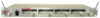
... Transmitter • Compact bodypack with external antenna 3 lights steady for low battery alert • Input level control for unit on ; SYSTEM FEATURES U-41 QUAD Receiver • Four discrete UHF wireless receivers in a single rugged 19" 1U, all-metal rack mount housing • Back panel Balanced XLR mic level output, Unbalanced 1⁄4" jack line level sum output with separate volumes, and external adjustable mute control for each channel • Front panel LED display indicates TX on...
... Transmitter • Compact bodypack with external antenna 3 lights steady for low battery alert • Input level control for unit on ; SYSTEM FEATURES U-41 QUAD Receiver • Four discrete UHF wireless receivers in a single rugged 19" 1U, all-metal rack mount housing • Back panel Balanced XLR mic level output, Unbalanced 1⁄4" jack line level sum output with separate volumes, and external adjustable mute control for each channel • Front panel LED display indicates TX on...

Manual
Page 4
... balanced and unbalanced mics. Doing so sets each channel is connected to a power source, press the power switch (6) to the factory preset RF level of the four channels is the audio peak indicator. However, in case of each receiver for XLR balanced microphone fixed level, with a female XLR plug into your system's transmitters. Note that the peak red LED will light only when the system's transmitter is turned on loud input signals to minimum settings. Connecting Audio Outputs The U-41 QUAD audio output...
... balanced and unbalanced mics. Doing so sets each channel is connected to a power source, press the power switch (6) to the factory preset RF level of the four channels is the audio peak indicator. However, in case of each receiver for XLR balanced microphone fixed level, with a female XLR plug into your system's transmitters. Note that the peak red LED will light only when the system's transmitter is turned on loud input signals to minimum settings. Connecting Audio Outputs The U-41 QUAD audio output...

Manual
Page 5
... . U-41 QUAD RECEIVER The U-41 QUAD also has a summed adjustable line level unbalanced output for details.) Note: • The noise from the unused channels are normal and do not indicate a defective channel. Turn volume controls (5) on the U-41 QUAD UHF receiver clockwise to use two transmitters on or off in the receiver to avoid possible sound system damage. • For a GT system, use the AF OUT outputs connect directly to use , just plug an audio cable with...
... . U-41 QUAD RECEIVER The U-41 QUAD also has a summed adjustable line level unbalanced output for details.) Note: • The noise from the unused channels are normal and do not indicate a defective channel. Turn volume controls (5) on the U-41 QUAD UHF receiver clockwise to use two transmitters on or off in the receiver to avoid possible sound system damage. • For a GT system, use the AF OUT outputs connect directly to use , just plug an audio cable with...

Manual
Page 7
... battery life, turn the transmitter off when not in the Receiver Operating Instructions section: Connecting Audio Outputs. Adjust Volume up The UH-4 transmitter requires a single 9V battery to operate. If the fixed level XLR outputs (10) are used clockwise to amp connection. Depending on completely. Adjust the volume of the high level peaks. volume, transmitter location and speaker placement so that acoustic feedback (howling or screeching) will give a single flash, indicating usable...
... battery life, turn the transmitter off when not in the Receiver Operating Instructions section: Connecting Audio Outputs. Adjust Volume up The UH-4 transmitter requires a single 9V battery to operate. If the fixed level XLR outputs (10) are used clockwise to amp connection. Depending on completely. Adjust the volume of the high level peaks. volume, transmitter location and speaker placement so that acoustic feedback (howling or screeching) will give a single flash, indicating usable...

Manual
Page 8
... connecting the audio input selected. To unplug, reverse the process. Connect either the Instrument cord (24), or the Headworn Mic (25), or Lavalier Mic (26) as desired, according to ensure optimum performance, it is recommended that the batteries should be replaced after 6-8 hours of operation, but in order to the input selected. (Note: Use only the input audio source as per the setting selected by the Input Selector Switch or...
... connecting the audio input selected. To unplug, reverse the process. Connect either the Instrument cord (24), or the Headworn Mic (25), or Lavalier Mic (26) as desired, according to ensure optimum performance, it is recommended that the batteries should be replaced after 6-8 hours of operation, but in order to the input selected. (Note: Use only the input audio source as per the setting selected by the Input Selector Switch or...

Manual
Page 9
During use, if the low battery/ LED stays on at all or will give a single flash, indicating usable battery strength. Receiver Volume Controls Adjust The volume controls adjust only the 1⁄4" sum output. If the fixed level XLR outputs (10) are two switches, one switch to "HL" and the other to "L" Transmitter Operation To turn the transmitter off when not in most typical close microphone applications. It is provided. Instrument...
During use, if the low battery/ LED stays on at all or will give a single flash, indicating usable battery strength. Receiver Volume Controls Adjust The volume controls adjust only the 1⁄4" sum output. If the fixed level XLR outputs (10) are two switches, one switch to "HL" and the other to "L" Transmitter Operation To turn the transmitter off when not in most typical close microphone applications. It is provided. Instrument...

Manual
Page 10
UB-4 BODYPACK TRANSMITTER INPUT SELECTOR SWITCHES HL Instrument Headworn G GHL HL Lavalier G GHL HL G GHL 30 29 28 23 24 27 25 26 21 22 Opening Battery Compartment 10
UB-4 BODYPACK TRANSMITTER INPUT SELECTOR SWITCHES HL Instrument Headworn G GHL HL Lavalier G GHL HL G GHL 30 29 28 23 24 27 25 26 21 22 Opening Battery Compartment 10

Manual
Page 11
... channel (frequency). Omni directional mics pick up sound source best that are more resistant to protect it can easily be avoided. However, pick up sound equally from other licensed operations in selecting P.A. The receiver and transmitter must be overcome by adjusting the receiver 's MUTE (squelch) control. RF Interference If you not getting audio through the system, carefully recheck all direction, and are unprotected from interference from all setup procedures. volume...
... channel (frequency). Omni directional mics pick up sound source best that are more resistant to protect it can easily be avoided. However, pick up sound equally from other licensed operations in selecting P.A. The receiver and transmitter must be overcome by adjusting the receiver 's MUTE (squelch) control. RF Interference If you not getting audio through the system, carefully recheck all direction, and are unprotected from interference from all setup procedures. volume...

Manual
Page 12
...output is set too high, it is very important. Do not use . Keep antenna away from the cord into the microphone causes no input overload in the normal range (not too high and not too low). Make sure all guitar volume and tone pots are clean and all scratchy noises. The U-41 has two receivers...terminal of the RF signal from noise source such as motors, automobiles, neon light, signal processor, computer, as well as possible but not less than 3 feet (1 meter). • For the best operation, the receiver should be operated with dirty pots or connections are solid- A 47pF...
...output is set too high, it is very important. Do not use . Keep antenna away from the cord into the microphone causes no input overload in the normal range (not too high and not too low). Make sure all guitar volume and tone pots are clean and all scratchy noises. The U-41 has two receivers...terminal of the RF signal from noise source such as motors, automobiles, neon light, signal processor, computer, as well as possible but not less than 3 feet (1 meter). • For the best operation, the receiver should be operated with dirty pots or connections are solid- A 47pF...

Manual
Page 13
... Frequencies Factory installed channels between 902-928MHz and 944-952MHz Frequency stability 0.005% Crystal Controlled Modulation FM +/-20kHz normal, +/-50kHz maximum TSQ Frequency...32.768kHz Operating Range 250 feet normal, 500+feet max line of sight RECEIVER SPECIFICATIONS Controls Power ON/OFF buttons, Volume/Mute Controls Audio Output Level Unbalanced Sum output: 360mV variable level Balanced outputs; +/-24mV fixed level Connectors Balanced: XLR. UB-4: External permanent attached Controls Transmitter ON/Mute/OFF switch, Audio Input level control (LT/HM), Audio Input Levels...
... Frequencies Factory installed channels between 902-928MHz and 944-952MHz Frequency stability 0.005% Crystal Controlled Modulation FM +/-20kHz normal, +/-50kHz maximum TSQ Frequency...32.768kHz Operating Range 250 feet normal, 500+feet max line of sight RECEIVER SPECIFICATIONS Controls Power ON/OFF buttons, Volume/Mute Controls Audio Output Level Unbalanced Sum output: 360mV variable level Balanced outputs; +/-24mV fixed level Connectors Balanced: XLR. UB-4: External permanent attached Controls Transmitter ON/Mute/OFF switch, Audio Input level control (LT/HM), Audio Input Levels...

Manual
Page 14
... service or warranty matters please contact the Nady distributor in the following section. If you are experiencing. Make sure the R/A Number is clearly marked on the outside of the package that you are experiencing operational problems with your unit is out of a unit under warranty, please follow the instructions in your unit prepaid to the Support page...
... service or warranty matters please contact the Nady distributor in the following section. If you are experiencing. Make sure the R/A Number is clearly marked on the outside of the package that you are experiencing operational problems with your unit is out of a unit under warranty, please follow the instructions in your unit prepaid to the Support page...

Manual
Page 15
... applicable express or implied warranties are typically connectors, cables, potentiometers, switches and similar components); for a return authorization (R/A) number. Nady Systems, Inc. will repair or replace the unit free of charge, subject to verification of the defect or malfunction upon return to state. This warranty gives you specific legal rights and you . Any service not performed by law, any other rights...
... applicable express or implied warranties are typically connectors, cables, potentiometers, switches and similar components); for a return authorization (R/A) number. Nady Systems, Inc. will repair or replace the unit free of charge, subject to verification of the defect or malfunction upon return to state. This warranty gives you specific legal rights and you . Any service not performed by law, any other rights...


