Nady U-800 Support Question
Nady U-800 Support Question
Find answers below for this question about Nady U-800.Need a Nady U-800 manual? We have 1 online manual for this item!
Question posted by bkigar on December 2nd, 2015
Unmuting Nady U-800
we have two Nady u-800 units and the body pack transmitters both will not unmute. as well the RF signal indicator shows the rceiver is getting a signal but it is low. even when within a metre.
Current Answers


Related Nady U-800 Manual Pages
Manual - Page 1
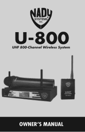
U-800
UHF 800-Channel Wireless System
OWNER'S MANUAL
Manual - Page 2
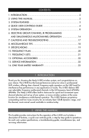
... system, or many wireless systems at the same location for each unit, system specifications, a troubleshooting guide, miscellaneous tips, and servicing information.
2 SERVICE INFORMATION 22 14. SYSTEM FEATURES 3 4. FREQUENCY PLAN 20 11. MISCELLANEOUS TIPS 18 9. INTRODUCTION
Thank you for choosing the Nady U-800 wireless system, and congratulations on the UHF band for an industry...
Manual - Page 3
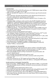
... handling noise • 800 easily selectable channels via IR Sync download for easy synchronization with receiver's
selected channel • Easy accessible input level adjustment for optimum sound • Power On/Off and Audio Mute switch allows convenient audio muting with the transmitter "ON" • Bicolor LED status indicator for unit "ON" and for low battery alert "ON...
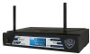
Manual - Page 4
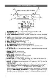
...indicates frequency in progress 11. MUTE ICON indicates audio muted 7. AF INDICATOR displays received Audio level 8. LCD DISPLAY shows receiver current status 6. 4. MUTE LEVEL shows muting level 14. POWER BUTTON BUTTON push in to -transmitter... will
4 RF INDICATOR displays received radio signal level 9. A/B INDICATORS indicates diversity A or B antenna reception when
transmitter is in ...
Manual - Page 5
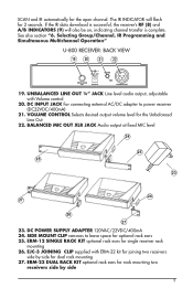
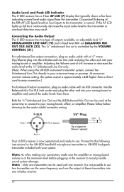
.... U NBALANCED LINE OUT ¼" JACK Line level audio output, adjustable with ERM-22 kit for joining two receivers
side-by side
5 SCAN and IR automatically for dual rack mounting 27. The IR INDICATOR will also be on, indicating channel transfer is successful, the receiver's RF (8) and A/B INDICATORS (9) will flash for rack mounting two
receivers side...
Manual - Page 6
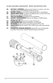
LOW BATTERY LED indicates the batteries are weak (red) 35. POWER ON LED indicates the transmitter ON (green) 34. UH-800 HANDHELD TRANSMITTER: FRONT AND BOTTOM VIEW
28. MIC BALL/ ANTENNA windscreen also functions as antenna, so for linking the
transmitter to the receiver during use
29. TWO AA BATTERIES operating from two AA batteries 32. BATTERY COMPARTMENT...
Manual - Page 7
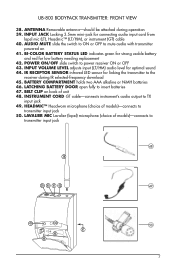
...low battery needing replacement 42. L AVALIER MIC Lavalier (lapel) microphone (choice of unit 48. I NPUT JACK Locking 3.5mm mini-jack for optimal sound 44. UB-800 BODYPACK TRANSMITTER: FRONT VIEW
38. ANTENNA Removable antenna-should be attached during IR selected-frequency download 45. I -COLOR BATTERY STATUS LED indicates... (LT/HM) audio level for connecting audio input cord from
lapel...
Manual - Page 8
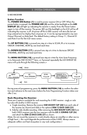
...performance of high heat - Press the Power button again to turn off . It can be off indicating the receiver is off the receiver. The UP BUTTON (16) is pressed one step at a ...LCD DISPLAY (5) menu will light up indicating the receiver is used to the next menu before the Auto Programming Function takes over after 5 sec. SYSTEM OPERATION
U-800 RECEIVER
Button Function The POWER ON Button ...
Manual - Page 9
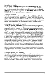
...18), then push UP BUTTON (16) to lock; Adjusting Antennas The U-800 has two permanently attached, flexible elbow ANTENNAS (3) for minimum squelch level-maximum ...signal RF INDICATOR (8) or the diversity A or B INDICATOR (9) flickers or stays on the back of -sight (no obstructions) between the receiver antennas and the transmitter at maximum sensitivity and operating range (i.e. If the transmitter...
Manual - Page 10
...in the receiver to the transmitter or
overload distortion may result. Audio Level and Peak The U-800 receiver has a 5
LbEaSDrYAISnFTdELiCMcaDtOo(7rP)EdRiAspTlIaOy Nthat
typically
shows
a
few
bars
indicating normal level audio signal from there. Please follow below drawing for the UH-800 handheld microphone transmitter or UB-800 bodypack transmitter included with a ¼" mono (Tip...
Manual - Page 11
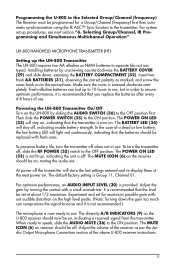
... use . The MUTE ICON (6) on , indicating a received signal from the transmitter. The POWER ON LED (33) will light red continuously, indicating that the level be replaced with a small screwdriver. To preserve battery life, turn the transmitter off, slide the RF POWER (35) switch to the ON position. The diversity A/B INDICATORS (9) on the U-800 receiver should now be on...
Manual - Page 12
... , indicating a received RF signal from the transmitter. During normal operation with the unit powered on the UB-800 by the BATTERY STATUS LED (41) lit RED. Adjust the volume of -sight between the transmitter and the receiver whenever possible. Note: Avoid acoustic feedback (howling or screeching) by the Mic tube housing only for power ON/OFF and audio...
Manual - Page 13
...'s RF INDICATOR (8) and diversity A/B INDICATOR (9) should now be on receiver should now be avoided. Operating the UB-800 Transmitter The POWER ON/OFF SWITCH (42) and the AUDIO MUTE...indicating the ON position is now ready to OFF again.
During normal operation with the unit powered on , muting the audio out. The MUTE ICON (6) on , indicating a received RF signal from the transmitter...
Manual - Page 14

... cable mini plug's outer ring counterclockwise. SELECTING GROUP/CHANNEL, IR PROGRAMMING AND SIMULTANEOUS MULTICHANNEL OPERATION
Note: Note: The transmitter should be adjusted on the instrument as selected for suitable level. Connecting Input Audio Source Lapel/Head Mic Uses (UB-800 LT/HM) The mini 3.5mm locking INPUT JACK (39) is for connecting the...
Manual - Page 17
... not cause harmful interference; Also confirm that the receiver and transmitter must operate at a low power level (not in front of wireless microphone systems, and these rules are not getting audio through the system, carefully re-check all end users of the microphone selected. RF Interference and Finding Open Channels The FCC mandates the following...
Manual - Page 18
...tone pots to ground terminal of the attached audio mixer, causing distortion. Also, since batteries ...transmitters are solid. Do not mix new and old batteries. • Position the receiver so that it has the least possible obstructions between them for a long time can reflect away or shield the incoming RF signal.
• If the receiver's volume control is set too low, the overall signal...
Manual - Page 19
SPECIFICATIONS
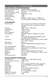
U-800 OVERALL SYSTEM PERFORMANCE
Operating Frequency Range 470MHz-510MHz, two Bands
Freq. 9. Synthesized
(800 channels switchable) 25kHz/step
PLL system frequency stability
Manual - Page 20
... Band 1: 470.000MHz-489.975MHz Band 2: 490.000MHz-509.975 MHz
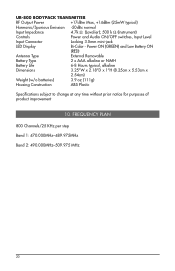
20 UB-800 BODYPACK TRANSMITTER
RF Output Power
+17dBm Max, +14dBm (25mW typical)
Harmonic/Spurious Emission -50dBc normal
Input Impedance
4.7k Ω (Lavalier); 500 k Ω (Instrument)
Controls
Power and Audio ON/OFF switches, Input Level
Input Connector
Locking 3.5mm mini-jack
LED Display...
Manual - Page 21
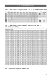
...800
Group 18 477.300 477.750 478.350 479.350 480.300 481.800
Group 19 483.300 483.750 484.350 485.100 486.300 487.800...800
Groups 1B-1F 470.000 470.025 470.050 : : : :
EVERY 25KHz : : :
489.925 489.950 489.975
Band 1: U-800...470.800 ...471.800 ...472.800 ...473.800 ...474.800 ...475.800 ...476.800 ....800 ...478.800 ...479.800 ....800 ....800 ....800 ...483.800 ...484.800 ....800 ....800 ....800 ...488.800 ...800 489.825 489.850 489.875 489.900 489...
Manual - Page 22
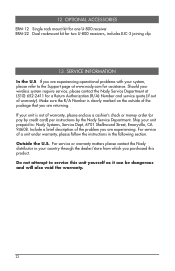
... : Nady Systems, Service Dept, 6701 Shellmound Street, Emeryville, CA 94608. Ship your country through the dealer/store from which you are returning. Include a brief description of the problem you are experiencing. OPTIONAL ACCESSORIES
ERM-12 Single rack mount kit for one U-800 receiver ERM-22 Dual rackmount kit for assistance. Should your unit...
Similar Questions


Where Can You Buya New Power Supply For The Nada Ald-800
Need power cordfor a NADA ald-800 Model NO AD-0920r with input of 120 volt ac 60Hz 8 w. Output of 9V...
Need power cordfor a NADA ald-800 Model NO AD-0920r with input of 120 volt ac 60Hz 8 w. Output of 9V...
(Posted by Dolpterry 1 year ago)