
42PD2/50PD1
Page 7
... of the Package ...9 OPTIONS ...9 Setup Procedure ...10 Part Names and Functions Front View ...12 Side View Terminal Board L/R ...13 Remote Controller ...14 Battery Installation and Replacement ...15 Operating Range / Using the wired remote control mode 16 Making the DIP Switch Settings DIP Switch Functions and Settings 17 Power Management Function ...18 Power...
... of the Package ...9 OPTIONS ...9 Setup Procedure ...10 Part Names and Functions Front View ...12 Side View Terminal Board L/R ...13 Remote Controller ...14 Battery Installation and Replacement ...15 Operating Range / Using the wired remote control mode 16 Making the DIP Switch Settings DIP Switch Functions and Settings 17 Power Management Function ...18 Power...
42PD2/50PD1
Page 9
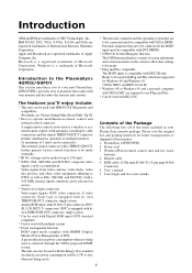
...used is achieved through the VESA-proposed DPMS system. settings can be made for future transportation or shipment of this monitor. 1. Wireless/Wired remote control unit and two AAA batteries 4. User' s manual 7. Ready to be used with Plug and Play which case power consumption will... items included in your monitor and describes the features and controls. * The personal computer and the operating system that are trademarks of NEC Technologies, Inc. The unit can be connected.) The external control connector with a THROUGH OUT feature permits various control functions to be ...
...used is achieved through the VESA-proposed DPMS system. settings can be made for future transportation or shipment of this monitor. 1. Wireless/Wired remote control unit and two AAA batteries 4. User' s manual 7. Ready to be used with Plug and Play which case power consumption will... items included in your monitor and describes the features and controls. * The personal computer and the operating system that are trademarks of NEC Technologies, Inc. The unit can be connected.) The external control connector with a THROUGH OUT feature permits various control functions to be ...
42PD2/50PD1
Page 10
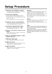
... procedures could result in the wired arrangement, connect the supplied remote control cable. 4. This monitor cannot be used without one unit, maximum.) 3. MODEL # PX-42VPU1-ST STAND IS REQUIRED FOR PERMANENT TABLETOP INSTALLATION. Product warranty...PERMANENT INSTALLATION. Setup Procedure 1. Connect the equipment Set the termination switch (75Ω/high impedance). Install the remote control batteries. * To use , see "Before Use" and "Observe the Following," then install properly. 2. Determine... to the installer. Notice: This monitor requires the use a trained, authorized NEC dealer.
... procedures could result in the wired arrangement, connect the supplied remote control cable. 4. This monitor cannot be used without one unit, maximum.) 3. MODEL # PX-42VPU1-ST STAND IS REQUIRED FOR PERMANENT TABLETOP INSTALLATION. Product warranty...PERMANENT INSTALLATION. Setup Procedure 1. Connect the equipment Set the termination switch (75Ω/high impedance). Install the remote control batteries. * To use , see "Before Use" and "Observe the Following," then install properly. 2. Determine... to the installer. Notice: This monitor requires the use a trained, authorized NEC dealer.
42PD2/50PD1
Page 11
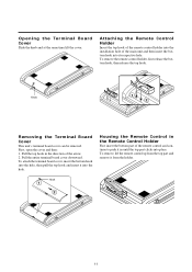
... the bottom hook, then release the top hook. To remove, lift the remote control up from the holder. Attaching the Remote Control Holder Insert the top hook of the remote control holder into the installation hole of the remote control and continue to push it from the top part and remove it in... until the top part clicks into place. Pull the entire terminal board cover downward. Housing the Remote Control in the direction of the arrow. 2. Pull the top hook in the Remote Control Holder First insert the bottom part of the main unit and then insert the bottom hook into the...
... the bottom hook, then release the top hook. To remove, lift the remote control up from the holder. Attaching the Remote Control Holder Insert the top hook of the remote control holder into the installation hole of the remote control and continue to push it from the top part and remove it in... until the top part clicks into place. Pull the entire terminal board cover downward. Housing the Remote Control in the direction of the arrow. 2. Pull the top hook in the Remote Control Holder First insert the bottom part of the main unit and then insert the bottom hook into the...

42PD2/50PD1
Page 12
... power on/standby or power management. 5 UP button Functions as the (v) button in the on-screen display (OSM) mode. 2 Remote control sensor Receives the signal from the remote control (when using the wireless remote control). 6 DOWN button Functions as the (w) button in the on-screen display (OSM) mode. 3 VIDEO button Switches to the...
... power on/standby or power management. 5 UP button Functions as the (v) button in the on-screen display (OSM) mode. 2 Remote control sensor Receives the signal from the remote control (when using the wireless remote control). 6 DOWN button Functions as the (w) button in the on-screen display (OSM) mode. 3 VIDEO button Switches to the...
42PD2/50PD1
Page 13
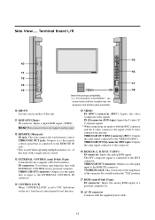
...IN connector. 14 CONTROL LOCK When "CONTROL LOCK" is set to the H/CS connector. THROUGH OUT connector: Outputs as is the signal input to the REMOTE IN jack. * This is connected to "ON", the buttons on the set's front bezel control panel do not function. 15 VIDEO IN [BNC] ...connector (BNC): Inputs the video (composite video signal). IN connector: Used when operating this unit) with a single remote control. 13 EXTERNAL CONTROL (mini D-Sub 15 pin) Controlled by the computer's RS-232C interface. The H/V composite signal is used in the "75Ω" ...
...IN connector. 14 CONTROL LOCK When "CONTROL LOCK" is set to the H/CS connector. THROUGH OUT connector: Outputs as is the signal input to the REMOTE IN jack. * This is connected to "ON", the buttons on the set's front bezel control panel do not function. 15 VIDEO IN [BNC] ...connector (BNC): Inputs the video (composite video signal). IN connector: Used when operating this unit) with a single remote control. 13 EXTERNAL CONTROL (mini D-Sub 15 pin) Controlled by the computer's RS-232C interface. The H/V composite signal is used in the "75Ω" ...

42PD2/50PD1
Page 14
...: Exits the on-screen adjustments. Press this button during the display of the video signal. (Does not function in the PAL or SECAM settings.) 14 Remote Controller 16 17 4 6 7 8 9 10 11 12 14 POWER OFF POWER ON RGB 2 RGB 1 RGB 3 VIDEO POSITION / CONTR OL EXIT PROCEED RGB/VIDEO CONTRAST BRIGHT VIDEO...
...: Exits the on-screen adjustments. Press this button during the display of the video signal. (Does not function in the PAL or SECAM settings.) 14 Remote Controller 16 17 4 6 7 8 9 10 11 12 14 POWER OFF POWER ON RGB 2 RGB 1 RGB 3 VIDEO POSITION / CONTR OL EXIT PROCEED RGB/VIDEO CONTRAST BRIGHT VIDEO...

42PD2/50PD1
Page 15
... ID number that was set with ID SELECT. 16 Remote control transmitter: Transmits the remote control signal. (Used with the wireless remote control.) 17 Remote jack: Connects the supplied remote control cable when used as a wired remote control. 1. Press and open the cover. 2. Battery Installation and Replacement The remote control is powered by two 1.5V AAA batteries...
... ID number that was set with ID SELECT. 16 Remote control transmitter: Transmits the remote control signal. (Used with the wireless remote control.) 17 Remote jack: Connects the supplied remote control cable when used as a wired remote control. 1. Press and open the cover. 2. Battery Installation and Replacement The remote control is powered by two 1.5V AAA batteries...
42PD2/50PD1
Page 16
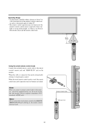
...BRIGHT VIDEO COLOR TINT SHARPNESS VISUAL NORMAL RASTER NORMAL ID SELECT CLEAR Using the wired remote control mode Connect the included remote control cable to wired remote control. When the cable is used, the remote control unit can be operated even if no batteries are loaded. If doing so...VIDEO CONTRAST BRIGHT VIDEO COLOR TINT SHARPNESS VISUAL NORMAL RASTER NORMAL ID SELECT CLEAR When the wired remote control mode is connected, the mode automatically switches to the remote control's remote jack and "REMOTE IN" jack on the monitor. Note: When you do not do this, this monitor will...
...BRIGHT VIDEO COLOR TINT SHARPNESS VISUAL NORMAL RASTER NORMAL ID SELECT CLEAR Using the wired remote control mode Connect the included remote control cable to wired remote control. When the cable is used, the remote control unit can be operated even if no batteries are loaded. If doing so...VIDEO CONTRAST BRIGHT VIDEO COLOR TINT SHARPNESS VISUAL NORMAL RASTER NORMAL ID SELECT CLEAR When the wired remote control mode is connected, the mode automatically switches to the remote control's remote jack and "REMOTE IN" jack on the monitor. Note: When you do not do this, this monitor will...

42PD2/50PD1
Page 17
...input sync signals. * When this setting. Switch position ON ON OFF OFF Note: When both pins No. 1 and No. 2 are settings of the wireless remote control signal is to be recognized automatically. Pin Nos. 3 and 4 Sync Control Settings * These are set "ON" the synchronization may control them at the ... * Set to "ON" when performing adjustments and viewing displays with something fine and pointed such as a miniature screwdriver or the tip of the wired remote control is not related to this unit is set to "OFF" when displays are moved up or down with the on -green) Switch position No...
...input sync signals. * When this setting. Switch position ON ON OFF OFF Note: When both pins No. 1 and No. 2 are settings of the wireless remote control signal is to be recognized automatically. Pin Nos. 3 and 4 Sync Control Settings * These are set "ON" the synchronization may control them at the ... * Set to "ON" when performing adjustments and viewing displays with something fine and pointed such as a miniature screwdriver or the tip of the wired remote control is not related to this unit is set to "OFF" when displays are moved up or down with the on -green) Switch position No...

42PD2/50PD1
Page 18
.... * Suspend mode The suspend mode is set when the vertical sync signal from the personal computer is not input. For information about 4 seconds Remote control in standby mode Power cord not connected * Standby suspend, off in about the power management setting method, see the video when the power ...Orange Orange Orange Not lit Notes ---- When preparing to display a personal computer screen, check that the personal computer power is set by the remote control. 18 When the personal computer power is off mode is on the VESA DPMS and DVI DMPM system. When there is no TMDS ...
.... * Suspend mode The suspend mode is set when the vertical sync signal from the personal computer is not input. For information about 4 seconds Remote control in standby mode Power cord not connected * Standby suspend, off in about the power management setting method, see the video when the power ...Orange Orange Orange Not lit Notes ---- When preparing to display a personal computer screen, check that the personal computer power is set by the remote control. 18 When the personal computer power is off mode is on the VESA DPMS and DVI DMPM system. When there is no TMDS ...

42PD2/50PD1
Page 21
... no signal loss, do not loop out to more than 3 other units should be set only on the last unit. Note: When looping from one remote control. 1. All other devices (maximum 4 units when taking the first unit into consideration). To pass the VIDEO IN (BNC-type) or S-VIDEO signals, connect... OUT RGBH/V (RGBCS) to the external equipment. Note: "Plug and Play" is not available for the RGB2 BNC terminals. Daisy-chaining Your monitors The REMOTE IN/OUT terminals allow you to control multiple monitors using one unit to the next, make sure that the 75ohm termination switch is set in...
... no signal loss, do not loop out to more than 3 other units should be set only on the last unit. Note: When looping from one remote control. 1. All other devices (maximum 4 units when taking the first unit into consideration). To pass the VIDEO IN (BNC-type) or S-VIDEO signals, connect... OUT RGBH/V (RGBCS) to the external equipment. Note: "Plug and Play" is not available for the RGB2 BNC terminals. Daisy-chaining Your monitors The REMOTE IN/OUT terminals allow you to control multiple monitors using one unit to the next, make sure that the 75ohm termination switch is set in...
42PD2/50PD1
Page 22
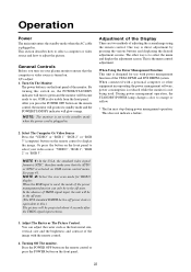
...changes color to display the image. Select The Computer Or Video Source Press the "VIDEO" or "RGB 1" "RGB 2" or "RGB 3"(computer) button on the remote control to orange or yellow. * The fan may stop during power management operation. See page 41. In the absence of the image with a personal computer... press the POWER button on OSM system control menu. After you turn to use with power management function of adjusting the screen/image using the remote control. NOTE: The monitor is set to adjust the picture. You can only be in . General Controls Before you press the POWER OFF...
...changes color to display the image. Select The Computer Or Video Source Press the "VIDEO" or "RGB 1" "RGB 2" or "RGB 3"(computer) button on the remote control to orange or yellow. * The fan may stop during power management operation. See page 41. In the absence of the image with a personal computer... press the POWER button on OSM system control menu. After you turn to use with power management function of adjusting the screen/image using the remote control. NOTE: The monitor is set to adjust the picture. You can only be in . General Controls Before you press the POWER OFF...

42PD2/50PD1
Page 23
..., FINE PICTURE, H/V-POSITION 1, H/V-POSITION 2, HWIDTH (Multiple Screens only), V-HEIGHT (Multiple Screens only) and OSM location. 1. Adjustment of the Display (Direct) Press the buttons of the remote control to adjust the H/V Positions. 23 PROCEED Adjustment display of the up Move left Move right Move down position V-POSITION wMOVE DOWN MOVE UP v Adjustment...
..., FINE PICTURE, H/V-POSITION 1, H/V-POSITION 2, HWIDTH (Multiple Screens only), V-HEIGHT (Multiple Screens only) and OSM location. 1. Adjustment of the Display (Direct) Press the buttons of the remote control to adjust the H/V Positions. 23 PROCEED Adjustment display of the up Move left Move right Move down position V-POSITION wMOVE DOWN MOVE UP v Adjustment...

42PD2/50PD1
Page 27
... 1 RGB 3 VIDEO POSITION / CONTR OL EXIT PROCEED RGB/VIDEO CONTRAST BRIGHT VIDEO COLOR TINT SHARPNESS VISUAL NORMAL RASTER NORMAL ID SELECT CLEAR Adjust using the remote control buttons. V-FREQ. Press during the display of the On-screen Display Main menu SOURCE INFO. VISUAL NORMAL button or RASTER NORMAL button Resets the...
... 1 RGB 3 VIDEO POSITION / CONTR OL EXIT PROCEED RGB/VIDEO CONTRAST BRIGHT VIDEO COLOR TINT SHARPNESS VISUAL NORMAL RASTER NORMAL ID SELECT CLEAR Adjust using the remote control buttons. V-FREQ. Press during the display of the On-screen Display Main menu SOURCE INFO. VISUAL NORMAL button or RASTER NORMAL button Resets the...

42PD2/50PD1
Page 40
... 2099, Month: JAN to DEC, Day: 01 to 31 Hours: 00 to 24, Minutes: 00 to set , the LED will flash orange every 3 seconds during remote control standby. Icon (11) PRESENT TIME DATE : 1999. Use the v / w buttons to move to each of the second page. DEC 10 TIME : 22 : 30 SET...
... 2099, Month: JAN to DEC, Day: 01 to 31 Hours: 00 to 24, Minutes: 00 to set , the LED will flash orange every 3 seconds during remote control standby. Icon (11) PRESENT TIME DATE : 1999. Use the v / w buttons to move to each of the second page. DEC 10 TIME : 22 : 30 SET...

42PD2/50PD1
Page 42
... buttons change the following input modes: VIDEO, RGB1 through RGB3, INV, WT. 42 Auto Timer Screen Note: •INV provides an inverse image of the remote control CLEAR button will work for the last input selected. Return to the main menu EXIT * To delete the main menu, press the EXIT button...
... buttons change the following input modes: VIDEO, RGB1 through RGB3, INV, WT. 42 Auto Timer Screen Note: •INV provides an inverse image of the remote control CLEAR button will work for the last input selected. Return to the main menu EXIT * To delete the main menu, press the EXIT button...
42PD2/50PD1
Page 45
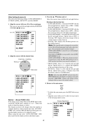
...: Selecting ALL RESET and pressing the PROCEED button will display a warning screen and pressing "PROCEED" further will change all white pattern to 256 with the remote control or CLEAR button. Previous Page Screen Icon (15) SOURCE INFO. About RGB3 ADJ If the image is 1) → Adjusts the brightness of the non...
...: Selecting ALL RESET and pressing the PROCEED button will display a warning screen and pressing "PROCEED" further will change all white pattern to 256 with the remote control or CLEAR button. Previous Page Screen Icon (15) SOURCE INFO. About RGB3 ADJ If the image is 1) → Adjusts the brightness of the non...

42PD2/50PD1
Page 46
...EXIT button twice. Note that have been set, the priority order will go UP 1. Return to switch the numbers from 1 through 4. * A press of the remote control CLEAR button causes a reset. (Initial value is ALL) Note: When both ID numbers have been set for Allotting ID Numbers to Multiple Screens/Each...ID SELECT MENU VIDEO WALL NO : 1 SET NO : 256 46 Numbers go DOWN Numbers go off when the EXIT button is valid regardless of the remote control This displays the ID selection screen. ID SELECT * Selects the ID number for each monitor in a Multiple screen so that each monitor. * ...
...EXIT button twice. Note that have been set, the priority order will go UP 1. Return to switch the numbers from 1 through 4. * A press of the remote control CLEAR button causes a reset. (Initial value is ALL) Note: When both ID numbers have been set for Allotting ID Numbers to Multiple Screens/Each...ID SELECT MENU VIDEO WALL NO : 1 SET NO : 256 46 Numbers go DOWN Numbers go off when the EXIT button is valid regardless of the remote control This displays the ID selection screen. ID SELECT * Selects the ID number for each monitor in a Multiple screen so that each monitor. * ...
42PD2/50PD1
Page 47
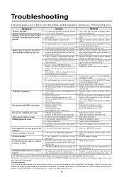
... is blinking in the timer operation; Check pin assignments and connections. • Adjust the tint and color. • Turn on when the remote controller's power button is pressed. this happens., turn on the computer's power. • Connect source to the monitor. • Operate the...'s power cord plugged into a power outlet? • Are all the monitor's indicators off . Cable interconnections. The remote cable is cut off the monitor immediately and contact your NEC dealer for 60 minutes. Switch to ON or connect to the proper resolution. • Check the input signal. &#...
... is blinking in the timer operation; Check pin assignments and connections. • Adjust the tint and color. • Turn on when the remote controller's power button is pressed. this happens., turn on the computer's power. • Connect source to the monitor. • Operate the...'s power cord plugged into a power outlet? • Are all the monitor's indicators off . Cable interconnections. The remote cable is cut off the monitor immediately and contact your NEC dealer for 60 minutes. Switch to ON or connect to the proper resolution. • Check the input signal. &#...


