
External Controls
Page 4
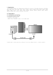
II. I. Preparation 2. Connectors and wiring 2.1 RS-232C Remote control Connector: 9-pin D-Sub Cable: Cross (reversed) cable or null modem cable (Please refer "Controlling the LCD monitor via RS-232C Remote control" on User's manual.) (4/145) Application This document defines the communications method for control of the NEC LCD monitor, MultiSync P404 /P484 /P554 /V404 /V484 /V554/ V404-T/ V484-T/ V554-T/ P654Q/ P754Q/ V554Q/ V654Q/ V754Q/ V864Q/ V984Q/ C651Q/ C751Q/ C861Q/ C981Q/ UN462A/ UN462VA/ UN492S/ UN492VS/ UN552/ UN552V/ UN552S/ UN552VS when using an external controller.
II. I. Preparation 2. Connectors and wiring 2.1 RS-232C Remote control Connector: 9-pin D-Sub Cable: Cross (reversed) cable or null modem cable (Please refer "Controlling the LCD monitor via RS-232C Remote control" on User's manual.) (4/145) Application This document defines the communications method for control of the NEC LCD monitor, MultiSync P404 /P484 /P554 /V404 /V484 /V554/ V404-T/ V484-T/ V554-T/ P654Q/ P754Q/ V554Q/ V654Q/ V754Q/ V864Q/ V984Q/ C651Q/ C751Q/ C861Q/ C981Q/ UN462A/ UN462VA/ UN492S/ UN492VS/ UN552/ UN552V/ UN552S/ UN552VS when using an external controller.
Users Manual - English
Page 3
...Radio-TV Interference Problems." This booklet is a trademark or registered trademark of America, Inc. U.S. Responsible Party: NEC Display Solutions of NEC Display Solutions, Ltd. MultiSync is available from that to the following two conditions. (1) This device may not ...particular installation. Use of Product: Display Monitor Equipment Classification: Class B Peripheral Model: C751Q C881Q C981Q SUPPLIER'S DECLARATION OF CONFORMITY This device complies with ferrite core. NEC is a trademark of their respective owners. All other brands and product names are designed...
...Radio-TV Interference Problems." This booklet is a trademark or registered trademark of America, Inc. U.S. Responsible Party: NEC Display Solutions of NEC Display Solutions, Ltd. MultiSync is available from that to the following two conditions. (1) This device may not ...particular installation. Use of Product: Display Monitor Equipment Classification: Class B Peripheral Model: C751Q C881Q C981Q SUPPLIER'S DECLARATION OF CONFORMITY This device complies with ferrite core. NEC is a trademark of their respective owners. All other brands and product names are designed...
Users Manual - English
Page 7
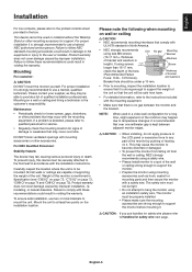
... edges. Mount the unit to support the weight of the unit so that there is mentioned in Specification (see "C651Q" on page 72, "C751Q" on page 73, "C861Q" on page 74 and "C981Q" on the installation location. This may happen due to mount the unit. CAUTION:... technician. Please contact your supplier, as hook, eyebolt or mounting parts and then secure the monitor with UL1678 standard in North America. • NEC strongly recommends using an installation safety wire. This device cannot be mounted. If a problem is strongly recommended to qualified personnel for service. •...
... edges. Mount the unit to support the weight of the unit so that there is mentioned in Specification (see "C651Q" on page 72, "C751Q" on page 73, "C861Q" on page 74 and "C981Q" on the installation location. This may happen due to mount the unit. CAUTION:... technician. Please contact your supplier, as hook, eyebolt or mounting parts and then secure the monitor with UL1678 standard in North America. • NEC strongly recommends using an installation safety wire. This device cannot be mounted. If a problem is strongly recommended to qualified personnel for service. •...
Users Manual - English
Page 9
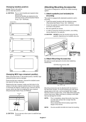
...8226; In order to aid in mounting. • Install the eyebolt brackets with the VESA mounting system. 1. VESA Mounting Interface (M8) Changing NEC logo ornament position When using only the eyebolts. NOTE: You can be changed. CAUTION: DO NOT mount the monitor using the monitor in the ...be attached with the screws, which are attached by the removed screws. (Recommended Fasten Force: 139 - 189 N•cm) C651Q/C751Q C861Q Attaching Mounting Accessories The monitor is equipped with attachable eyebolts to move the monitor into eyebolt holes in eyebolt brackets as a blanket ...
...8226; In order to aid in mounting. • Install the eyebolt brackets with the VESA mounting system. 1. VESA Mounting Interface (M8) Changing NEC logo ornament position When using only the eyebolts. NOTE: You can be changed. CAUTION: DO NOT mount the monitor using the monitor in the ...be attached with the screws, which are attached by the removed screws. (Recommended Fasten Force: 139 - 189 N•cm) C651Q/C751Q C861Q Attaching Mounting Accessories The monitor is equipped with attachable eyebolts to move the monitor into eyebolt holes in eyebolt brackets as a blanket ...

OLR-751 Installation Guide
Page 1
Rev 1.0 Page 1 Page 1 Page 2 Page 2 Page 3 2.0 Purpose 2.1 This procedure describes the steps to install the IR touch overlay onto the C751Q display. 3.0 Notes and Warnings 3.1 Prior to ensure the touch frame does not bend or torque. 3.5 Once the touch screen is installed, do not ...lift the monitor by grasping or holding the touch screen overlay. 3.6 Contact NEC Display Solutions support if you have any questions or require additional installation guidance support. 500 Park Boulevard, Suite 1100 Itasca, IL 60143 Phone: (800) ...
Rev 1.0 Page 1 Page 1 Page 2 Page 2 Page 3 2.0 Purpose 2.1 This procedure describes the steps to install the IR touch overlay onto the C751Q display. 3.0 Notes and Warnings 3.1 Prior to ensure the touch frame does not bend or torque. 3.5 Once the touch screen is installed, do not ...lift the monitor by grasping or holding the touch screen overlay. 3.6 Contact NEC Display Solutions support if you have any questions or require additional installation guidance support. 500 Park Boulevard, Suite 1100 Itasca, IL 60143 Phone: (800) ...

OLR-751 Installation Guide
Page 2
USB Extension Cable www.necdisplay.com OLR-751 2 IR Touch Overlay Installation Guide for the OLR-751 4.0 Equipment (1) C751Q IR Overlay NEC Display Solutions of America, Inc. Rev 1.0 (1) Spare #6-32 Philips flathead machine screw 5.0 Dimensional Drawings (1) 10ft.
USB Extension Cable www.necdisplay.com OLR-751 2 IR Touch Overlay Installation Guide for the OLR-751 4.0 Equipment (1) C751Q IR Overlay NEC Display Solutions of America, Inc. Rev 1.0 (1) Spare #6-32 Philips flathead machine screw 5.0 Dimensional Drawings (1) 10ft.

Installation Guide
Page 1
...is not intended to be used as a reference guide to be a step-by 25.4. • Distances may vary ±5%. V754Q/C751Q Installation Guide NEC Display Solutions of 13 All mounts should make secure contact to wood studs. • Distances are in inches, for millimeters multiply by step... procedure for a design or installation. www.necdisplay.com V754Q/C751Q Page 1 of America, Inc. [Ver.1.0] Contents: Product Description and ...
...is not intended to be used as a reference guide to be a step-by 25.4. • Distances may vary ±5%. V754Q/C751Q Installation Guide NEC Display Solutions of 13 All mounts should make secure contact to wood studs. • Distances are in inches, for millimeters multiply by step... procedure for a design or installation. www.necdisplay.com V754Q/C751Q Page 1 of America, Inc. [Ver.1.0] Contents: Product Description and ...

Installation Guide
Page 2
NEC Display Solutions of 13 Contact NEC for proper ventilation. NOTE: • The ventilation space should not be covered or closed off at the front of the opening needs to be covered, other means of ventilation will need to be incorporated into the design. If for some reason the opening . Carrying Handle Positioning: www.necdisplay.com V754Q/C751Q Page 2 of America, Inc. Ventilation Recommendations: Dimensions below are minimum required for design review and recommendations.
NEC Display Solutions of 13 Contact NEC for proper ventilation. NOTE: • The ventilation space should not be covered or closed off at the front of the opening needs to be covered, other means of ventilation will need to be incorporated into the design. If for some reason the opening . Carrying Handle Positioning: www.necdisplay.com V754Q/C751Q Page 2 of America, Inc. Ventilation Recommendations: Dimensions below are minimum required for design review and recommendations.

Installation Guide
Page 3
www.necdisplay.com V754Q/C751Q Page 3 of America, Inc. Display Dimensions: NEC Display Solutions of 13
www.necdisplay.com V754Q/C751Q Page 3 of America, Inc. Display Dimensions: NEC Display Solutions of 13

Installation Guide
Page 4
www.necdisplay.com V754Q/C751Q Page 4 of America, Inc. Display Dimensions (cont.): NEC Display Solutions of 13 NEC strongly recommends using screws longer than 15-17mm, please check the depth of the bracket and washers in length). If using size M8 screws (15-17mm + the thickness of the hole.
www.necdisplay.com V754Q/C751Q Page 4 of America, Inc. Display Dimensions (cont.): NEC Display Solutions of 13 NEC strongly recommends using screws longer than 15-17mm, please check the depth of the bracket and washers in length). If using size M8 screws (15-17mm + the thickness of the hole.

Installation Guide
Page 5
Display Dimensions (with optional ST-801 stand): NEC Display Solutions of 13 www.necdisplay.com V754Q/C751Q Page 5 of America, Inc.
Display Dimensions (with optional ST-801 stand): NEC Display Solutions of 13 www.necdisplay.com V754Q/C751Q Page 5 of America, Inc.

Installation Guide
Page 6
www.necdisplay.com V754Q/C751Q Page 6 of America, Inc. Table Top Stand Dimensions (ST-801): NEC Display Solutions of 13
www.necdisplay.com V754Q/C751Q Page 6 of America, Inc. Table Top Stand Dimensions (ST-801): NEC Display Solutions of 13

Installation Guide
Page 7
Optional Slim Wall Mount (WMK-3255S): NEC Display Solutions of 13 Optional Large Wall Mount (WMK-6598): www.necdisplay.com V754Q/C751Q Page 7 of America, Inc.
Optional Slim Wall Mount (WMK-3255S): NEC Display Solutions of 13 Optional Large Wall Mount (WMK-6598): www.necdisplay.com V754Q/C751Q Page 7 of America, Inc.

Installation Guide
Page 8
www.necdisplay.com V754Q/C751Q Page 8 of America, Inc. Optional Standard Wall Mount (WMK-3257): NEC Display Solutions of 13
www.necdisplay.com V754Q/C751Q Page 8 of America, Inc. Optional Standard Wall Mount (WMK-3257): NEC Display Solutions of 13

Installation Guide
Page 10
Compute Module Integration: • Door on the back of the display can be opened by loosening captive screws. • Separate IO Board is necessary to accompany RPi Compute Module in unit www.necdisplay.com V754Q/C751Q Page 10 of America, Inc. NEC Display Solutions of 13
Compute Module Integration: • Door on the back of the display can be opened by loosening captive screws. • Separate IO Board is necessary to accompany RPi Compute Module in unit www.necdisplay.com V754Q/C751Q Page 10 of America, Inc. NEC Display Solutions of 13

Installation Guide
Page 11
www.necdisplay.com V754Q/C751Q Page 11 of America, Inc. Side (Rotated) ASCII Common Commands: • This monitor supports common ASCII control commands with many other NEC projectors. Input Panel: Bottom NEC Display Solutions of 13 For more information on this, please see our website.
www.necdisplay.com V754Q/C751Q Page 11 of America, Inc. Side (Rotated) ASCII Common Commands: • This monitor supports common ASCII control commands with many other NEC projectors. Input Panel: Bottom NEC Display Solutions of 13 For more information on this, please see our website.

Installation Guide
Page 13
Browser Control: Information and control can also be available through the HTTP browser control menu. In order to accomplish this, type: http:// NEC Display Solutions of America, Inc.
Browser Control: Information and control can also be available through the HTTP browser control menu. In order to accomplish this, type: http:// NEC Display Solutions of America, Inc.


