
User Manual
Page 4
... to rise and escape. REFRAIN FROM OPENING THE CABINET AS THERE ARE HIGH-VOLTAGE COMPONENTS INSIDE. Warnings and Safety Precaution This plasma monitor is required. The plasma display panel consists of this unit has been included. For operating safety and to avoid damage to make sure there is not...BE FULLY INSERTED. Do not use this way the warranty will be used over a long period. 6. If the problem persists, contact your plasma monitor and keep the manual handy for 60 minutes to authorized Service Centers. Avoid damage to the power cord, and do not produce light or ...
... to rise and escape. REFRAIN FROM OPENING THE CABINET AS THERE ARE HIGH-VOLTAGE COMPONENTS INSIDE. Warnings and Safety Precaution This plasma monitor is required. The plasma display panel consists of this unit has been included. For operating safety and to avoid damage to make sure there is not...BE FULLY INSERTED. Do not use this way the warranty will be used over a long period. 6. If the problem persists, contact your plasma monitor and keep the manual handy for 60 minutes to authorized Service Centers. Avoid damage to the power cord, and do not produce light or ...
User Manual
Page 5
... the panel surface as the continuous display of a static image over the life of a Plasma Display Panel. 8. Plasma monitor cleaning procedure: 1. To protect your investment in this plasma monitor, please adhere to the following measures to reduce the likelihood of phosphor burn: * Lower ... dealer. 7. Continued operation at line voltages greater than 100240 Volts AC will best suit your dealer for other gas plasma displays, plasma monitors can result in long term use or continuous operation take the following guidelines and recommendations for minimizing the occurrence of image...
... the panel surface as the continuous display of a static image over the life of a Plasma Display Panel. 8. Plasma monitor cleaning procedure: 1. To protect your investment in this plasma monitor, please adhere to the following measures to reduce the likelihood of phosphor burn: * Lower ... dealer. 7. Continued operation at line voltages greater than 100240 Volts AC will best suit your dealer for other gas plasma displays, plasma monitors can result in long term use or continuous operation take the following guidelines and recommendations for minimizing the occurrence of image...

User Manual
Page 6
... E-7 Installation E-8 Connecting Your PC or Macintosh Computer E-9 Connections with Computer Signals ....... Contents How to Attach Options to the Plasma Monitor E-2 The features you'll enjoy include E-2 Contents of the audio connectors ........ E-14 Wide Screen Operation with Equipment that have...for the sides of the screen ..... E-14 When viewing a high definition video source ........ E-1 Introduction E-2 Introduction to the Plasma Monitor .. E-9 Connecting Your Document Camera E-9 Connecting Your VCR or Laser Disc Player E-9 Connecting Your DVD Player E-9 Pin Assignments...
... E-7 Installation E-8 Connecting Your PC or Macintosh Computer E-9 Connections with Computer Signals ....... Contents How to Attach Options to the Plasma Monitor E-2 The features you'll enjoy include E-2 Contents of the audio connectors ........ E-14 Wide Screen Operation with Equipment that have...for the sides of the screen ..... E-14 When viewing a high definition video source ........ E-1 Introduction E-2 Introduction to the Plasma Monitor .. E-9 Connecting Your Document Camera E-9 Connecting Your VCR or Laser Disc Player E-9 Connecting Your DVD Player E-9 Pin Assignments...

User Manual
Page 7
... 50mm (2") 50mm (2") below when installing. Wall 50mm (2") E-1 50mm (2") 50mm (2") How to Attach Options to the Plasma Monitor You can attach your optional mounts or stand to the plasma monitor in damage to the equipment or injury to scratch the screen face. * Do not touch or hold the screen face...allow heat to disperse, leave space between surrounding objects as not to the installer. Lay the protective sheet, which was wrapped around the monitor when it was packaged, beneath the screen surface so as shown on its own. Product warranty does not cover damage caused by improper...
... 50mm (2") 50mm (2") below when installing. Wall 50mm (2") E-1 50mm (2") 50mm (2") How to Attach Options to the Plasma Monitor You can attach your optional mounts or stand to the plasma monitor in damage to the equipment or injury to scratch the screen face. * Do not touch or hold the screen face...allow heat to disperse, leave space between surrounding objects as not to the installer. Lay the protective sheet, which was wrapped around the monitor when it was packaged, beneath the screen surface so as shown on its own. Product warranty does not cover damage caused by improper...
User Manual
Page 8
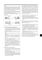
...using the safety fitting mount screws. Contents of the Package Ⅺ Plasma monitor Ⅺ Power cord Ⅺ Remote control with our special CCF. • 42VP4: Installed AR (Anti-Reflection) Filter 42VP4D: Installed AG (Anti-Glare) Filter • 42VP4: Body color ... unit • Stand • Attachable speakers E-2 Introduction Introduction to the Plasma Monitor This plasma monitor is 2 types, black or silver. • 42VP4, 42VP4D: 89 mm / 3.5 inch thin • 42VP4, 42VP4D: 28.5 kg / 62.8 lbs light • 42VP4, 42VP4D: 853ן480 pixels • Flicker -
...using the safety fitting mount screws. Contents of the Package Ⅺ Plasma monitor Ⅺ Power cord Ⅺ Remote control with our special CCF. • 42VP4: Installed AR (Anti-Reflection) Filter 42VP4D: Installed AG (Anti-Glare) Filter • 42VP4: Body color ... unit • Stand • Attachable speakers E-2 Introduction Introduction to the Plasma Monitor This plasma monitor is 2 types, black or silver. • 42VP4, 42VP4D: 89 mm / 3.5 inch thin • 42VP4, 42VP4D: 28.5 kg / 62.8 lbs light • 42VP4, 42VP4D: 853ן480 pixels • Flicker -

User Manual
Page 14
.... · SCART2...Connect R/G/B to the RGB1 terminal. To obtain the special cable as well as for Macintosh To Mini D-Sub 15 pin connector on the plasma monitor Personal computer with a digital signal output VD RGB 1 (IN / OUT ) AUDIO 3 R L (MONO) RGB 3 DV I N / OUT) VIDEO 3 AUDIO 1 L (MONO) R DVD1 / HD1 ...Player VIDEO 1- 3 To video inputs on -screen manager. Please refer to page E-25 for selection of the correct mode in the on the plasma monitor DVD Player Document Camera • For Y/CB/Cr, connect to the DVD1 or DVD2 terminals. • For SCART, this unit provides three...
.... · SCART2...Connect R/G/B to the RGB1 terminal. To obtain the special cable as well as for Macintosh To Mini D-Sub 15 pin connector on the plasma monitor Personal computer with a digital signal output VD RGB 1 (IN / OUT ) AUDIO 3 R L (MONO) RGB 3 DV I N / OUT) VIDEO 3 AUDIO 1 L (MONO) R DVD1 / HD1 ...Player VIDEO 1- 3 To video inputs on -screen manager. Please refer to page E-25 for selection of the correct mode in the on the plasma monitor DVD Player Document Camera • For Y/CB/Cr, connect to the DVD1 or DVD2 terminals. • For SCART, this unit provides three...

User Manual
Page 15
... video port, if necessary. 5. To maintain display quality, use the DVD-player's S-Video output. Turn on the plasma monitor and the computer. 6. Turn on the plasma monitor and the DVD player. Turn off the power to your VCR or laser disc player owner's manual for more information ... your RCA cable to the video output connector on your plasma monitor. To do so, simply: 1. To do so, simply: 1. The plasma monitor supports the signals described on your plasma monitor. Connecting Your DVD Player You can connect your plasma monitor to the Video input on page E-43. If you to...
... video port, if necessary. 5. To maintain display quality, use the DVD-player's S-Video output. Turn on the plasma monitor and the computer. 6. Turn on the plasma monitor and the DVD player. Turn off the power to your VCR or laser disc player owner's manual for more information ... your RCA cable to the video output connector on your plasma monitor. To do so, simply: 1. To do so, simply: 1. The plasma monitor supports the signals described on your plasma monitor. Connecting Your DVD Player You can connect your plasma monitor to the Video input on page E-43. If you to...

User Manual
Page 48
... 01H 01H 82H DFH 80H 60H C1H 01H 02H 83H Note: Contact your local dealer for a full list of the plasma monitor by external equipment. External equipment e.g., Personal computer Display Connector on the plasma monitor side: EXTERNAL CONTROL connector. Use a crossed (reverse) cable. Connections Connections are made as described below. External Control Application These...
... 01H 01H 82H DFH 80H 60H C1H 01H 02H 83H Note: Contact your local dealer for a full list of the plasma monitor by external equipment. External equipment e.g., Personal computer Display Connector on the plasma monitor side: EXTERNAL CONTROL connector. Use a crossed (reverse) cable. Connections Connections are made as described below. External Control Application These...

User Manual
Page 55
... Name 1 No Connection 2 RXD (Receive data) 3 TXD (Transmit data) 4 DTR (DTE side ready) 5 GND 6 DSR (DCE side ready) 7 RTS (Ready to send) 8 CTS (Clear to NEC plasma monitors and communications control from external equipment. Application These specifications are applicable to send) 9 No Connection 2 "Please also support the command of VP series and refer...
... Name 1 No Connection 2 RXD (Receive data) 3 TXD (Transmit data) 4 DTR (DTE side ready) 5 GND 6 DSR (DCE side ready) 7 RTS (Ready to send) 8 CTS (Clear to NEC plasma monitors and communications control from external equipment. Application These specifications are applicable to send) 9 No Connection 2 "Please also support the command of VP series and refer...

User Manual
Page 57
... making it operate using ID, bit1 and bit0 are numbers used to identify the equipment that is to be connected. 60H is used for the plasma monitor and 80H is FH (as follows.
... making it operate using ID, bit1 and bit0 are numbers used to identify the equipment that is to be connected. 60H is used for the plasma monitor and 80H is FH (as follows.

User Manual
Page 58
When supporting Set ID by the command 1, 4 bits of higher ranks of Set ID are set up . * Set ID : it is the apparatus number assigned to each plasma monitor. 5 When supporting Set ID by the command 1, 4 bits of low ranks of Set ID are set up . 2) Unit ID 2: Indicates the equipment receiving the signal. 1) Unit ID 1: Indicates the equipment sending the signal.
When supporting Set ID by the command 1, 4 bits of higher ranks of Set ID are set up . * Set ID : it is the apparatus number assigned to each plasma monitor. 5 When supporting Set ID by the command 1, 4 bits of low ranks of Set ID are set up . 2) Unit ID 2: Indicates the equipment receiving the signal. 1) Unit ID 1: Indicates the equipment sending the signal.

User Manual
Page 60
...= "5", the value of ID-1=4 is as "5" is shown below . The control method of the set by Set ID When controlling two or more sets of plasma monitors, if the command using Set ID is used as a master(etc PC) is set to 50, and it assumes that ID is shaken by AUTO... order to be performed depending on connection with external control apparatus. 7 It is not based on ID but is the POWER ON command to the plasma monitor which set used , it . *:Control by the above command performs a 4th page multi SPLIT display. The example of the set ID as follows...
...= "5", the value of ID-1=4 is as "5" is shown below . The control method of the set by Set ID When controlling two or more sets of plasma monitors, if the command using Set ID is used as a master(etc PC) is set to 50, and it assumes that ID is shaken by AUTO... order to be performed depending on connection with external control apparatus. 7 It is not based on ID but is the POWER ON command to the plasma monitor which set used , it . *:Control by the above command performs a 4th page multi SPLIT display. The example of the set ID as follows...

User Manual
Page 63
Transmission Data 9FH 80H 60H 4FH 00H CKS ACK The plasma monitor returns the following ACK when the power is switched off the power of the plasma monitor. Power ON Function The external control equipment switches on . 3FH 60H 80H 4EH 00H CKS NOTE: Do not set the Power ON or Power OFF... command continuously. 10 01. Transmission Data 9FH 80H 60H 4EH 00H CKS ACK The plasma monitor returns the following ACK when the power is switched on the power of the plasma monitor. Power OFF Function The external control equipment switches off . 3FH 60H 80H 4FH 00H CKS NOTE: Do ...
Transmission Data 9FH 80H 60H 4FH 00H CKS ACK The plasma monitor returns the following ACK when the power is switched off the power of the plasma monitor. Power ON Function The external control equipment switches on . 3FH 60H 80H 4EH 00H CKS NOTE: Do not set the Power ON or Power OFF... command continuously. 10 01. Transmission Data 9FH 80H 60H 4EH 00H CKS ACK The plasma monitor returns the following ACK when the power is switched on the power of the plasma monitor. Power OFF Function The external control equipment switches off . 3FH 60H 80H 4FH 00H CKS NOTE: Do ...

User Manual
Page 64
03. Input Switch Change Function The external control equipment switches the input of the plasma monitor. Transmission Data DFH 80H 60H 47H 01H DATA00 CKS DATA00 : Input Select 01H : Video1 02H : Video2 03H : Video3 05H : HD (HD1 or DTV or DTV1) 06H: HD2 (DTV2 or SCART1/SCART2) 07H : RGB1 / PC1 08H : RGB2 / PC2 0CH : RGB3 / PC3 0DH : HD3(SCART3) ACK The plasma monitor returns the following ACK when the input is switched. 3FH 60H 80H 47H 00H CKS 11
03. Input Switch Change Function The external control equipment switches the input of the plasma monitor. Transmission Data DFH 80H 60H 47H 01H DATA00 CKS DATA00 : Input Select 01H : Video1 02H : Video2 03H : Video3 05H : HD (HD1 or DTV or DTV1) 06H: HD2 (DTV2 or SCART1/SCART2) 07H : RGB1 / PC1 08H : RGB2 / PC2 0CH : RGB3 / PC3 0DH : HD3(SCART3) ACK The plasma monitor returns the following ACK when the input is switched. 3FH 60H 80H 47H 00H CKS 11

User Manual
Page 65
... Function The external control equipment switches on AUDIO Mute of the plasma monitor. VOLUME Gain Data Function The external control equipment changes the VOLUME gain data of the plasma monitor. AUDIO Mute OFF Function The external control equipment switches off AUDIO Mute of the plasma monitor. Transmission Data 9FH 80H 60H 3FH 00H CKS ACK 3FH...
... Function The external control equipment switches on AUDIO Mute of the plasma monitor. VOLUME Gain Data Function The external control equipment changes the VOLUME gain data of the plasma monitor. AUDIO Mute OFF Function The external control equipment switches off AUDIO Mute of the plasma monitor. Transmission Data 9FH 80H 60H 3FH 00H CKS ACK 3FH...
User Manual
Page 66
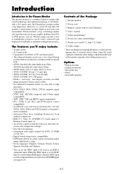
CONTRAST Gain Data Function The external control equipment changes the CONTRAST gain data of the plasma monitor. BRIGHT Gain Data Function The external control equipment changes the BRIGHT gain data of the plasma c Transmission Data DFH 80H 60H 7FH 03H DATA00 DATA01 DATA02 CKS DATA00 : USER PICTURE Gain Flag 01H DATA01 : CONTRAST Gain Flag...
CONTRAST Gain Data Function The external control equipment changes the CONTRAST gain data of the plasma monitor. BRIGHT Gain Data Function The external control equipment changes the BRIGHT gain data of the plasma c Transmission Data DFH 80H 60H 7FH 03H DATA00 DATA01 DATA02 CKS DATA00 : USER PICTURE Gain Flag 01H DATA01 : CONTRAST Gain Flag...
User Manual
Page 67
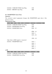
... PICTURE Gain Flag 01H DATA01 : BRIGHT Gain Flag 08H 09. SHARPNESS Gain Data Function The external control equipment changes the SHARPNESS gain data of the plasma monitor.
... PICTURE Gain Flag 01H DATA01 : BRIGHT Gain Flag 08H 09. SHARPNESS Gain Data Function The external control equipment changes the SHARPNESS gain data of the plasma monitor.
User Manual
Page 68
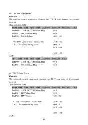
...) only during video. 00H : 0 01H : +01 : 20H : +32 ACK 15 COLOR Gain Data Function The external control equipment changes the COLOR gain data of the plasma monitor. TINT Gain Data Function The external control equipment changes the TINT gain data of the...
...) only during video. 00H : 0 01H : +01 : 20H : +32 ACK 15 COLOR Gain Data Function The external control equipment changes the COLOR gain data of the plasma monitor. TINT Gain Data Function The external control equipment changes the TINT gain data of the...

User Manual
Page 69
... THEATER1(It cannot choose in the still picture input of a personal computer.) 03H : THEATER2(It cannot choose in the still picture input of the plasma monitor. 7FH 60H 80H 7FH 02H DATA00 DATA01 CKS DATA00 : USER PICTURE Gain Flag 01H DATA01 : TINT Gain Flag 05H 12. COLOR TEMP SELECT Function... 01H : NORMAL 02H : THEATER1 03H : THEATER2 04H : Default 13. PICTURE MODE Select Function The external control equipment sets the picture mode of the plasma monitor. Transmission Data DFH 80H 60H 00H 01H DATA00 CKS DATA00 : 00H: low 01H: middle 02H: high 03H: middle low ACK 7FH 60H 80H 00H ...
... THEATER1(It cannot choose in the still picture input of a personal computer.) 03H : THEATER2(It cannot choose in the still picture input of the plasma monitor. 7FH 60H 80H 7FH 02H DATA00 DATA01 CKS DATA00 : USER PICTURE Gain Flag 01H DATA01 : TINT Gain Flag 05H 12. COLOR TEMP SELECT Function... 01H : NORMAL 02H : THEATER1 03H : THEATER2 04H : Default 13. PICTURE MODE Select Function The external control equipment sets the picture mode of the plasma monitor. Transmission Data DFH 80H 60H 00H 01H DATA00 CKS DATA00 : 00H: low 01H: middle 02H: high 03H: middle low ACK 7FH 60H 80H 00H ...

User Manual
Page 70
01H: middle 02H: high 03H: middle low 14. RED Gain Data Function The external control equipment changes the RED Gain Data of the plasma monitor. Transmission Data DFH 80H 60H 7FH 04H DATA00 to DATA03 CKS DATA00 : USER PICTURE Gain Flag 01H DATA01 : RED Gain Flag 01H DATA02 : RED Gain1(Bias) D8H : -40 : FFH : -01 00H : 0 01H : +01 : 1EH : +30 DATA03: RED Gain2(Drive) D8H : -40 : FFH : -01 00H : 0 01H : +01 : 1EH : +30 ACK 7FH 60H 80H 7FH 02H DATA00 DATA01 CKS DATA00 : USER PICTURE Gain Flag 01H DATA01 : RED Gain Flag 01H 17
01H: middle 02H: high 03H: middle low 14. RED Gain Data Function The external control equipment changes the RED Gain Data of the plasma monitor. Transmission Data DFH 80H 60H 7FH 04H DATA00 to DATA03 CKS DATA00 : USER PICTURE Gain Flag 01H DATA01 : RED Gain Flag 01H DATA02 : RED Gain1(Bias) D8H : -40 : FFH : -01 00H : 0 01H : +01 : 1EH : +30 DATA03: RED Gain2(Drive) D8H : -40 : FFH : -01 00H : 0 01H : +01 : 1EH : +30 ACK 7FH 60H 80H 7FH 02H DATA00 DATA01 CKS DATA00 : USER PICTURE Gain Flag 01H DATA01 : RED Gain Flag 01H 17


