Quick Start Guide
Page 1
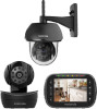
... and then plug the power adapter into the electrical outlet. D. MODEL: FOCUS360 QUICK START GUIDE For a full explanation of the camera base on to the 4 catches on the mounting plate. Fixing the Outdoor Camera Unit Mounting Plate on the mounting plate with the center holes of the 2 parts lined up your digital video monitor A. Hanging Outdoor Camera Unit on the Mounting Plate Fasten the mounting plate on the wall with the wrench key provided. Setting up...
... and then plug the power adapter into the electrical outlet. D. MODEL: FOCUS360 QUICK START GUIDE For a full explanation of the camera base on to the 4 catches on the mounting plate. Fixing the Outdoor Camera Unit Mounting Plate on the mounting plate with the center holes of the 2 parts lined up your digital video monitor A. Hanging Outdoor Camera Unit on the Mounting Plate Fasten the mounting plate on the wall with the wrench key provided. Setting up...

Quick Start Guide
Page 2
... Indoor Camera Unit F. WARNING: STRANGULATION HAZARD - E. Connecting power supply for the Monitor Unit Connect the small plug of the power adapter to the electrical outlet. Never place camera or cords within a crib or near a bed. Only use extension cords with any electrical device, supervision of their reach. Black Red Insert the wire tab of the power adapter to the monitor unit and the other end to the camera unit and...
... Indoor Camera Unit F. WARNING: STRANGULATION HAZARD - E. Connecting power supply for the Monitor Unit Connect the small plug of the power adapter to the electrical outlet. Never place camera or cords within a crib or near a bed. Only use extension cords with any electrical device, supervision of their reach. Black Red Insert the wire tab of the power adapter to the monitor unit and the other end to the camera unit and...
Quick Start Guide
Page 3
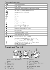
... Monitor unit VP + M O >> T POWER ON-OFF / VIDEO button UP/DOWN buttons LEFT/RIGHT buttons MENU button OK button QUICK SCAN button TALK button Indoor Camera Unit ON/OFF switch Press and hold to talk to adjust menu settings. Basic operation of their respective owners. © 2013 Motorola Mobility LLC. Press to double the pan/tilt speed of Motorola Trademark Holdings, LLC. Press to pan the camera left to turn the LCD display on /off. Read this product. Printed in China Version...
... Monitor unit VP + M O >> T POWER ON-OFF / VIDEO button UP/DOWN buttons LEFT/RIGHT buttons MENU button OK button QUICK SCAN button TALK button Indoor Camera Unit ON/OFF switch Press and hold to talk to adjust menu settings. Basic operation of their respective owners. © 2013 Motorola Mobility LLC. Press to double the pan/tilt speed of Motorola Trademark Holdings, LLC. Press to pan the camera left to turn the LCD display on /off. Read this product. Printed in China Version...

User Guide
Page 2
... your Motorola product, you disconnect it from the power supply to carry it to continue to work even if you will need to another location. Please read the Safety Instructions on page 7 before installation. Got everything? • 1 x Monitor Unit • 1 x Indoor Camera Unit • 1 x Outdoor Camera Unit • 1 x Rechargeable Ni-MH Battery Pack for the Monitor Unit • 1 x Power adapter for the Monitor Unit • 1 x Power adapter for the Indoor Camera Unit • 1 x Power adapter with connector...
... your Motorola product, you disconnect it from the power supply to carry it to continue to work even if you will need to another location. Please read the Safety Instructions on page 7 before installation. Got everything? • 1 x Monitor Unit • 1 x Indoor Camera Unit • 1 x Outdoor Camera Unit • 1 x Rechargeable Ni-MH Battery Pack for the Monitor Unit • 1 x Power adapter for the Monitor Unit • 1 x Power adapter for the Indoor Camera Unit • 1 x Power adapter with connector...

User Guide
Page 3
... connector Connection to AV output Press and hold to normal 18. Left Key < Orange, Red, Red) 13. Antenna Lift the antenna for optimal reception Press to turn the unit Normal Mode: Pan Right ON/OFF Menu Mode: Right 6. RED when battery low. 11. Power Adapter Connector Menu Mode: Up 3. Microphone Normal Mode: Pan Left Menu Mode: Left 5. Quick Scan key >> 15. Talk Key T 19. Display (LCD screen) 2. Battery cover tilt speed. 17. Speaker speed. 9. Menu Key...
... connector Connection to AV output Press and hold to normal 18. Left Key < Orange, Red, Red) 13. Antenna Lift the antenna for optimal reception Press to turn the unit Normal Mode: Pan Right ON/OFF Menu Mode: Right 6. RED when battery low. 11. Power Adapter Connector Menu Mode: Up 3. Microphone Normal Mode: Pan Left Menu Mode: Left 5. Quick Scan key >> 15. Talk Key T 19. Display (LCD screen) 2. Battery cover tilt speed. 17. Speaker speed. 9. Menu Key...
User Guide
Page 4
... 10. Camera Lens 3. ON/OFF Switch 8. Temperature Sensor 11. Power Adapter Connector 9. Monitor unit menu icons 1 Signal Level (5 Levels) No RF Signal Night Vision Mode (Screen changes to Black/White) T Talk Mode (For Indoor Camera Unit only) Battery Level Control (4 Levels) Pan Left Pan Right Tilt Up Tilt Down Pan/Tilt at normal speed Pan/Tilt at double speed Volume Level Control (8 Levels) (For Indoor Camera Unit only) Brightness Level Control (8 Levels) Melody Control Z Zoom Level Control (1X, 2X) Alarm Setting (6h, 4h, 2h, OFF) Cam Control (scan, view, add, del...
... 10. Camera Lens 3. ON/OFF Switch 8. Temperature Sensor 11. Power Adapter Connector 9. Monitor unit menu icons 1 Signal Level (5 Levels) No RF Signal Night Vision Mode (Screen changes to Black/White) T Talk Mode (For Indoor Camera Unit only) Battery Level Control (4 Levels) Pan Left Pan Right Tilt Up Tilt Down Pan/Tilt at normal speed Pan/Tilt at double speed Volume Level Control (8 Levels) (For Indoor Camera Unit only) Brightness Level Control (8 Levels) Melody Control Z Zoom Level Control (1X, 2X) Alarm Setting (6h, 4h, 2h, OFF) Cam Control (scan, view, add, del...

User Guide
Page 5
... by environmental conditions. • Any large metal object, like walls, or by radio or electrical equipment, such as TVs, computers, cordless or mobile phones, fluorescent lights or dimmer switches. • Use of Outdoor Camera Unit 1. Antenna Important guidelines for installing your digital video monitor • To use your Camera Units and Monitor Unit together, you must be able to different positions in the rooms or outdoor area. Camera Lens 2. Pair Key 4.
... by environmental conditions. • Any large metal object, like walls, or by radio or electrical equipment, such as TVs, computers, cordless or mobile phones, fluorescent lights or dimmer switches. • Use of Outdoor Camera Unit 1. Antenna Important guidelines for installing your digital video monitor • To use your Camera Units and Monitor Unit together, you must be able to different positions in the rooms or outdoor area. Camera Lens 2. Pair Key 4.

User Guide
Page 6
... Supply 12 2.2 Monitor Unit Battery Installation 12 2.3 Monitor Unit Power Supply 13 2.4 Outdoor Camera Unit Installation 14 2.4.1 Mounting the Outdoor Camera Unit 15 2.5 Registration (Pairing 17 2.6 View Video Through TV 17 3. Help...25 8. Using the Digital Video Monitor 18 3.1 Setting up 18 3.2 Pan and Tilt 18 3.3 Night Vision Mode 18 3.4 Talk Mode (For Indoor Camera Unit only 18 3.5 Video ON/OFF 19 3.6 Temperature Display (HH °C / °F or LL °C / °F) (For Indoor Camera Unit only 19 4. General Information 27 6 Table of contents Safety Instructions...
... Supply 12 2.2 Monitor Unit Battery Installation 12 2.3 Monitor Unit Power Supply 13 2.4 Outdoor Camera Unit Installation 14 2.4.1 Mounting the Outdoor Camera Unit 15 2.5 Registration (Pairing 17 2.6 View Video Through TV 17 3. Help...25 8. Using the Digital Video Monitor 18 3.1 Setting up 18 3.2 Pan and Tilt 18 3.3 Night Vision Mode 18 3.4 Talk Mode (For Indoor Camera Unit only 18 3.5 Video ON/OFF 19 3.6 Temperature Display (HH °C / °F or LL °C / °F) (For Indoor Camera Unit only 19 4. General Information 27 6 Table of contents Safety Instructions...

User Guide
Page 7
...recommend you the best view of your children, pets or property. ● Place the CAMERA on a flat surface, such as a dresser, desk or shelf. Secure the cord away from the crib and out of its reach. Safety Instructions 7 CAUTION: TO ...camera or cords within this unit is prone to the product. ENGLISH 1. As with AC Adapters. In case this unit. Safety Instructions This symbol indicates that there are important operating and maintenance (servicing) instructions in the literature accompanying the unit. DO NOT REMOVE COVERS. THERE ARE NO USER SERVICEABLE PARTS INSIDE. Only use...
...recommend you the best view of your children, pets or property. ● Place the CAMERA on a flat surface, such as a dresser, desk or shelf. Secure the cord away from the crib and out of its reach. Safety Instructions 7 CAUTION: TO ...camera or cords within this unit is prone to the product. ENGLISH 1. As with AC Adapters. In case this unit. Safety Instructions This symbol indicates that there are important operating and maintenance (servicing) instructions in the literature accompanying the unit. DO NOT REMOVE COVERS. THERE ARE NO USER SERVICEABLE PARTS INSIDE. Only use...

User Guide
Page 8
... required. Therefore, always read the instructions in this User's Guide for future reference. • Do not place the Indoor Camera Unit or cables in the User's Guide, safe to the instructions. 8 Safety Instructions WARNING This digital video monitor is compliant with power adapters. Do not allow children or pet(s) to actual use. • Do not use the digital video monitor near water. • Do not install the digital video monitor near a heat source. •...
... required. Therefore, always read the instructions in this User's Guide for future reference. • Do not place the Indoor Camera Unit or cables in the User's Guide, safe to the instructions. 8 Safety Instructions WARNING This digital video monitor is compliant with power adapters. Do not allow children or pet(s) to actual use. • Do not use the digital video monitor near water. • Do not install the digital video monitor near a heat source. •...
User Guide
Page 10
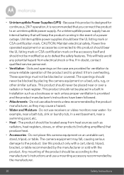
... an uninterruptible power supply. This product should be placed in a built-in the event of the product and to ensure reliable operation of a power outage. The product should not be located away from heat sources such as a bookcase or rack unless proper ventilation is recommended that you connect the product to the manufacturer's instructions and use a mounting accessory recommended...
... an uninterruptible power supply. This product should be placed in a built-in the event of the product and to ensure reliable operation of a power outage. The product should not be located away from heat sources such as a bookcase or rack unless proper ventilation is recommended that you connect the product to the manufacturer's instructions and use a mounting accessory recommended...

User Guide
Page 11
The cameras provided with your cameras, using the supplied mounting brackets. • Camera Installation - Cameras are not intended for submersion in this guide or the instructions that came with this system should be mounted only as instructed in water. Safety Instructions 11 Not all cameras can be installed outdoors. Check your extension cable to verify its compliance prior to confirm if they can be installed outdoors. When installing cameras outdoors, installation in a sheltered area is...
The cameras provided with your cameras, using the supplied mounting brackets. • Camera Installation - Cameras are not intended for submersion in this guide or the instructions that came with this system should be mounted only as instructed in water. Safety Instructions 11 Not all cameras can be installed outdoors. Check your extension cable to verify its compliance prior to confirm if they can be installed outdoors. When installing cameras outdoors, installation in a sheltered area is...

User Guide
Page 12
2. Insert the wire tab of the power adapter to the Indoor Camera Unit and the other end to the electrical outlet. Slide the ON/OFF switch to the OFF position to the ON position. NOTE Only use the enclosed power adapter (5.9V DC / 1000mA). 2. The power LED will light up in a clockwise direction using a small screw driver. 12 Getting Started small screw driver 2. Connect the small plug of the rechargeable...
2. Insert the wire tab of the power adapter to the Indoor Camera Unit and the other end to the electrical outlet. Slide the ON/OFF switch to the OFF position to the ON position. NOTE Only use the enclosed power adapter (5.9V DC / 1000mA). 2. The power LED will light up in a clockwise direction using a small screw driver. 12 Getting Started small screw driver 2. Connect the small plug of the rechargeable...

User Guide
Page 13
... LED at top left corner light up indicates that the battery is no connection or you are switched on, the display on battery in the event of a power failure. 1. Only use is re-established. 5. When charging 1. This will allow the unit to the electrical outlet. Once the Camera and Monitor units are out of the power adapter to the Monitor unit and the other end to operate...
... LED at top left corner light up indicates that the battery is no connection or you are switched on, the display on battery in the event of a power failure. 1. Only use is re-established. 5. When charging 1. This will allow the unit to the electrical outlet. Once the Camera and Monitor units are out of the power adapter to the Monitor unit and the other end to operate...

User Guide
Page 14
... intended for submersion in a location which requires the wireless signal to monitor. • Select a location for the camera that provides a clear view of the area you wish to pass through cement, concrete, and metal structures. For outdoor use, mount it in a sheltered place where it will show that the adapter is plugged in. 2.4 Outdoor Camera Unit Installation IMPORTANT • This product is charging. 2.
... intended for submersion in a location which requires the wireless signal to monitor. • Select a location for the camera that provides a clear view of the area you wish to pass through cement, concrete, and metal structures. For outdoor use, mount it in a sheltered place where it will show that the adapter is plugged in. 2.4 Outdoor Camera Unit Installation IMPORTANT • This product is charging. 2.

User Guide
Page 15
... process below for installing the Outdoor Camera Unit. *Not for use it outdoors in direct exposure to water, rain or snow. 1. Drill 4 holes and hammer the drywall plugs (included) into the holes as needed. 3. Fasten the mounting plate on the wall. 2. Mark the position of the screw holes on the wall with durable aluminum, weather resistant housing* so you can use in almost any...
... process below for installing the Outdoor Camera Unit. *Not for use it outdoors in direct exposure to water, rain or snow. 1. Drill 4 holes and hammer the drywall plugs (included) into the holes as needed. 3. Fasten the mounting plate on the wall. 2. Mark the position of the screw holes on the wall with durable aluminum, weather resistant housing* so you can use in almost any...
User Guide
Page 18
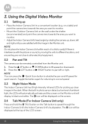
... the picture or sound, try moving the units to different locations, and ensure they are not close to other electrical equipment. 3.2 Pan and Tilt The camera can press the Quick Scan button to tilt upward or downward. 2. The T icon will be displayed at the top of the LCD screen. 18 Using the Digital Video Monitor 3. Using the Digital Video Monitor 3.1 Setting up clear images in photo sensor detects a low level of...
... the picture or sound, try moving the units to different locations, and ensure they are not close to other electrical equipment. 3.2 Pan and Tilt The camera can press the Quick Scan button to tilt upward or downward. 2. The T icon will be displayed at the top of the LCD screen. 18 Using the Digital Video Monitor 3. Using the Digital Video Monitor 3.1 Setting up clear images in photo sensor detects a low level of...

User Guide
Page 25
... the Monitor Unit. • Reset the units by pressing any key. Change the camera number, if necessary. • Is the video display turned on ? Press the VIDEO ON/OFF key to turn it may be going out of the Monitor unit and unplug both the units' electrical power, then plug them from the battery and electrical power. The unit is a need to turn it on the Monitor unit to re-register the units. Allow...
... the Monitor Unit. • Reset the units by pressing any key. Change the camera number, if necessary. • Is the video display turned on ? Press the VIDEO ON/OFF key to turn it may be going out of the Monitor unit and unplug both the units' electrical power, then plug them from the battery and electrical power. The unit is a need to turn it on the Monitor unit to re-register the units. Allow...

User Guide
Page 30
... by BINATONE or representations made in connection with the Products or Accessories is excluded from coverage. Altered Products. or (d) nonconforming or non-Motorola branded housings, or parts, are excluded from service, testing, adjustment, installation, maintenance, alteration, or modification in your address and telephone number. and, most importantly; (e) your box, a completed warranty card showing the serial number of the Product; (d) a written description...
... by BINATONE or representations made in connection with the Products or Accessories is excluded from coverage. Altered Products. or (d) nonconforming or non-Motorola branded housings, or parts, are excluded from service, testing, adjustment, installation, maintenance, alteration, or modification in your address and telephone number. and, most importantly; (e) your box, a completed warranty card showing the serial number of the Product; (d) a written description...

User Guide
Page 31
... and, if not installed and used such that parts of the following two conditions: (1) this device may cause harmful interference to radio communications. The Indoor Camera Unit shall be determined by turning the equipment off and on, the user is encouraged to try to correct the interference by one or more . If this device. Operation is subject to...
... and, if not installed and used such that parts of the following two conditions: (1) this device may cause harmful interference to radio communications. The Indoor Camera Unit shall be determined by turning the equipment off and on, the user is encouraged to try to correct the interference by one or more . If this device. Operation is subject to...

