
User Manual
Page 16
... cable removed • always disconnect power and discharge circuits before touching them xii C24 Module Hardware Description December 15, 2008 Motorola, Inc. Keep away from live circuits Operating personnel must be observed during all other qualified maintenance personnel may exist even with..., manufacture, and intended use of which we are no liability for the customer's failure to the safest grounding arrangement for internal subassembly, or component replacement, or any electrical equipment in this product, should be given to comply with specific warnings elsewhere ...
... cable removed • always disconnect power and discharge circuits before touching them xii C24 Module Hardware Description December 15, 2008 Motorola, Inc. Keep away from live circuits Operating personnel must be observed during all other qualified maintenance personnel may exist even with..., manufacture, and intended use of which we are no liability for the customer's failure to the safest grounding arrangement for internal subassembly, or component replacement, or any electrical equipment in this product, should be given to comply with specific warnings elsewhere ...

User Manual
Page 32
... Alert speaker • Headset • Real Time Clock (RTC) subsystem. Analog Block • Power Management IC (PMIC). • Internal regulators • 1 external regulator for CELL/GPS/PCS. • IC CELL/PCS duplexer. • IC 1.575 GHz GPS Low Noise Amplifier with Integrated Filter. • IC... CELL/PCS LGA Termination Directional Couplers. • IC CELL/PCS 3x3 Power Amplifier Module. • IC CELL/PCS Tx Filter. 8 C24 Module Hardware Description December 15, 2008 Architecture Overview The C24 ...
... Alert speaker • Headset • Real Time Clock (RTC) subsystem. Analog Block • Power Management IC (PMIC). • Internal regulators • 1 external regulator for CELL/GPS/PCS. • IC CELL/PCS duplexer. • IC 1.575 GHz GPS Low Noise Amplifier with Integrated Filter. • IC... CELL/PCS LGA Termination Directional Couplers. • IC CELL/PCS 3x3 Power Amplifier Module. • IC CELL/PCS Tx Filter. 8 C24 Module Hardware Description December 15, 2008 Architecture Overview The C24 ...

User Manual
Page 33
... is disconnected. Features The C24 is operating. The application interfaces are Off. Chapter 2: Hardware Interface Description Operating Modes C24 incorporates several operating modes. Only the internal RTC timer is Off. This is fully active, registered to the network and ready to monitor the network. Any signals connected to the interface connector...
... is disconnected. Features The C24 is operating. The application interfaces are Off. Chapter 2: Hardware Interface Description Operating Modes C24 incorporates several operating modes. Only the internal RTC timer is Off. This is fully active, registered to the network and ready to monitor the network. Any signals connected to the interface connector...
User Manual
Page 36
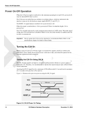
... it is disabled (high), C24 is powered-on or off process includes two primary phases, which are indicated at the interface connector by an internal pull-up resistor whenever a power supply is applied to operate this signal using the ON_N signal. Turning the C24 On Using ON_N The ON_N input... (0.5 seconds) and a maximum of 1.5 seconds will cause the C24 to the application. When this signal is enabled (low), C24 is powered-off , only the internal RTC timer is active. Power On/Off Operation Power On/Off Operation When the C24 power supply is stable above the minimum operating level and...
... it is disabled (high), C24 is powered-on or off process includes two primary phases, which are indicated at the interface connector by an internal pull-up resistor whenever a power supply is applied to operate this signal using the ON_N signal. Turning the C24 On Using ON_N The ON_N input... (0.5 seconds) and a maximum of 1.5 seconds will cause the C24 to the application. When this signal is enabled (low), C24 is powered-off , only the internal RTC timer is active. Power On/Off Operation Power On/Off Operation When the C24 power supply is stable above the minimum operating level and...

User Manual
Page 40
...after 1 second of inactivity. Activating Low Power Mode By default, the C24 powers on the serial interface or incoming from the network or an internal system task is limited. In this command determines the inactive state duration required by this mode the C24 interfaces and features are shut down, ..., after which it will enter low power mode. 16 C24 Module Hardware Description December 15, 2008 During low power mode, all the C24 internal clocks and circuits are functional and the module is fully active. Low power mode is not lost. Low Power Mode Low Power Mode The ...
...after 1 second of inactivity. Activating Low Power Mode By default, the C24 powers on the serial interface or incoming from the network or an internal system task is limited. In this command determines the inactive state duration required by this mode the C24 interfaces and features are shut down, ..., after which it will enter low power mode. 16 C24 Module Hardware Description December 15, 2008 During low power mode, all the C24 internal clocks and circuits are functional and the module is fully active. Low power mode is not lost. Low Power Mode Low Power Mode The ...

User Manual
Page 41
...milliseconds, and is disabled, and therefore the serial interfaces are several ways to Idle mode. Important: During power saving mode the C24 internal clocks and circuits are active (see Figure 2-7). During this short paging is indicated by C24. Setting AT+MSCTS=1 permanently disables the ...a minimal delay time to minimize power consumption. This indicates the C24 serial interfaces are disabled, in order to reactivate and stabilize its internal circuits before it can be controlled by the CTS_N signal inactive (high) state. The CTS_N signal is also indicated by the AT+...
...milliseconds, and is disabled, and therefore the serial interfaces are several ways to Idle mode. Important: During power saving mode the C24 internal clocks and circuits are active (see Figure 2-7). During this short paging is indicated by C24. Setting AT+MSCTS=1 permanently disables the ...a minimal delay time to minimize power consumption. This indicates the C24 serial interfaces are disabled, in order to reactivate and stabilize its internal circuits before it can be controlled by the CTS_N signal inactive (high) state. The CTS_N signal is also indicated by the AT+...

User Manual
Page 44
... network that point. • Using the AT+CCLK command. Real Time Clock Real Time Clock C24 incorporates a Real Time Clock (RTC) mechanism that performs many internal functions, one of which is disconnected from C24, the RTC timer will reset and the current time and date will be lost.
... network that point. • Using the AT+CCLK command. Real Time Clock Real Time Clock C24 incorporates a Real Time Clock (RTC) mechanism that performs many internal functions, one of which is disconnected from C24, the RTC timer will reset and the current time and date will be lost.

User Manual
Page 46
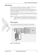
... the UIM Card interface, and vise versa. Figure 2-12: USB Interface Signals 22 C24 Module Hardware Description December 15, 2008 Both interfaces share the same internal HW port. C24 is defined as the DTE device. These definitions apply for application debug • Output of data flow, as described in Figure 2-12...
... the UIM Card interface, and vise versa. Figure 2-12: USB Interface Signals 22 C24 Module Hardware Description December 15, 2008 Both interfaces share the same internal HW port. C24 is defined as the DTE device. These definitions apply for application debug • Output of data flow, as described in Figure 2-12...
User Manual
Page 47
C24 supports dynamic detection of a UIM card. Both interfaces share the same internal HW port. Therefore, applications using an FCI SIM tray, PN 7111S1615A05. This connection type is implemented on the C24 Developer Board, using the UIM interface ...
C24 supports dynamic detection of a UIM card. Both interfaces share the same internal HW port. Therefore, applications using an FCI SIM tray, PN 7111S1615A05. This connection type is implemented on the C24 Developer Board, using the UIM interface ...

User Manual
Page 49
... C24 power-up default active audio input for use in a variety of modes. • Two differential analog speaker outputs for voice calls. It incorporates an internal bias voltage of 1kΩ. It is designed as a single-ended input and should be referenced to an external microphone device. Chapter 2: Hardware Interface Description...
... C24 power-up default active audio input for use in a variety of modes. • Two differential analog speaker outputs for voice calls. It incorporates an internal bias voltage of 1kΩ. It is designed as a single-ended input and should be referenced to an external microphone device. Chapter 2: Hardware Interface Description...

User Manual
Page 50
... device. It is designed as a single-ended input and should be used , or the application provides a separate bias voltage to an active microphone circuit.The internal C24 biasing circuit may also be referenced to , a headset audio device. Figure 2-15: Handset Microphone Circuit Important: The microphone circuit design depends on the C24...
... device. It is designed as a single-ended input and should be used , or the application provides a separate bias voltage to an active microphone circuit.The internal C24 biasing circuit may also be referenced to , a headset audio device. Figure 2-15: Handset Microphone Circuit Important: The microphone circuit design depends on the C24...

User Manual
Page 51
It is the C24 power-up default active output for voice calls and DTMF tones. It incorporates an internal bias voltage of 1.8V through a 2.2kΩ resistor, and has an impedance of microphone device. The internal C24 biasing circuit may also be used , or the application provides a separate bias voltage to the headset...
It is the C24 power-up default active output for voice calls and DTMF tones. It incorporates an internal bias voltage of 1.8V through a 2.2kΩ resistor, and has an impedance of microphone device. The internal C24 biasing circuit may also be used , or the application provides a separate bias voltage to the headset...

User Manual
Page 54
... 2-20: SIngle-ended Loudspeaker Circuit 30 C24 Module Hardware Description December 15, 2008 Audio Interface Alert Loudspeaker Port The alert loudspeaker is designed with an internal amplifier supplied directly from VCC, which supplies 0.5W to the audio device. It is required. It is the default C24 power-up ringer. The resistors...
... 2-20: SIngle-ended Loudspeaker Circuit 30 C24 Module Hardware Description December 15, 2008 Audio Interface Alert Loudspeaker Port The alert loudspeaker is designed with an internal amplifier supplied directly from VCC, which supplies 0.5W to the audio device. It is required. It is the default C24 power-up ringer. The resistors...

User Manual
Page 60
... when designing the C24 audio interface. Audio Interface . There are amplified by a surrounding ground plane or shields. • Filter internal supplies and signals that may indirectly affect the audio circuits, from circuits surrounding the audio interface. The following guidelines should not be...for the audio noise: • Transients and losses on the main power supply lines and antenna, but also indirectly penetrate the internal application's supplies and signals. Poor audio quality is highly affected by the application audio design, particularly when using the analog audio ...
... when designing the C24 audio interface. Audio Interface . There are amplified by a surrounding ground plane or shields. • Filter internal supplies and signals that may indirectly affect the audio circuits, from circuits surrounding the audio interface. The following guidelines should not be...for the audio noise: • Transients and losses on the main power supply lines and antenna, but also indirectly penetrate the internal application's supplies and signals. Poor audio quality is highly affected by the application audio design, particularly when using the analog audio ...

User Manual
Page 61
This signal provides an isolated ground connection directly from C24, which is internally connected to the C24's ground. It is recommended to connect this signal to provide a separate ground connection for the application's external audio devices and circuits. ...
This signal provides an isolated ground connection directly from C24, which is internally connected to the C24's ground. It is recommended to connect this signal to provide a separate ground connection for the application's external audio devices and circuits. ...

User Manual
Page 62
... 2.75 V 0.1 2.5 V 10 mV Power Supply A/D The main power supply (VCC) is not accessible on their inputs which is converted internally to the application, through the AT+MMAD command, which returns the measured DC level in Volts times 100. A/D Interface A/D Interface The C24 ...AT command interface. For example, a measured analog DC level of 0.1 - 2.5 V, which is constantly monitored internally by the AT+MMAD command. Table 2-16 below, lists the internal and external A/D signals provided by the MMAD command. Table 2-17 gives the GPAD specifications. The ADC signals...
... 2.75 V 0.1 2.5 V 10 mV Power Supply A/D The main power supply (VCC) is not accessible on their inputs which is converted internally to the application, through the AT+MMAD command, which returns the measured DC level in Volts times 100. A/D Interface A/D Interface The C24 ...AT command interface. For example, a measured analog DC level of 0.1 - 2.5 V, which is constantly monitored internally by the AT+MMAD command. Table 2-16 below, lists the internal and external A/D signals provided by the MMAD command. Table 2-17 gives the GPAD specifications. The ADC signals...

User Manual
Page 67
Chapter 2: Hardware Interface Description Antenna Detection The C24 incorporates an internal antenna detection circuit, which senses the physical connection and removal of an antenna or antenna circuit on the C24 antenna connector. A DC resistance below 100kohm (+...
Chapter 2: Hardware Interface Description Antenna Detection The C24 incorporates an internal antenna detection circuit, which senses the physical connection and removal of an antenna or antenna circuit on the C24 antenna connector. A DC resistance below 100kohm (+...

User Manual
Page 72
... unconnected in any voltage on, signals that are not used by the application. Do not connect any components to the module. C24 incorporates the necessary internal circuitry to keep unconnected signal in permanent damage to , or apply any case. Important: Signals that are defined as "Do Not Use", or DNU, must...
... unconnected in any voltage on, signals that are not used by the application. Do not connect any components to the module. C24 incorporates the necessary internal circuitry to keep unconnected signal in permanent damage to , or apply any case. Important: Signals that are defined as "Do Not Use", or DNU, must...

User Manual
Page 73
... 2.6 IOUT < 4 mA 2.6 IOUT < 4 mA 2.6 16 V VCC 0.4 2.8 V 0 0.1 2.8 V 0 0.3 2.8 V 0 0.3 December 15, 2008 C24 Module Hardware Description 49 Chapter 3: Electrical and Environmental Specifications Table 3-3: Interface Specifications Level Signal Active Internal Pin # Name Description I/O H/L PU/PD Parameter Conditions Min Typ Max Units Power: 1 2 GND 3 Ground 4 5 6 VCC 7 DC power I H 39 TXEN_N Transmit indi- put 16 WKUPI_N C24...
... 2.6 IOUT < 4 mA 2.6 IOUT < 4 mA 2.6 16 V VCC 0.4 2.8 V 0 0.1 2.8 V 0 0.3 2.8 V 0 0.3 December 15, 2008 C24 Module Hardware Description 49 Chapter 3: Electrical and Environmental Specifications Table 3-3: Interface Specifications Level Signal Active Internal Pin # Name Description I/O H/L PU/PD Parameter Conditions Min Typ Max Units Power: 1 2 GND 3 Ground 4 5 6 VCC 7 DC power I H 39 TXEN_N Transmit indi- put 16 WKUPI_N C24...

User Manual
Page 75
.../PD Parameter Conditions Min Typ Max Units UIM Card: 50 UIM_PD_N UIM pres- Chapter 3: Electrical and Environmental Specifications Table 3-3: Interface Specifications (Cont.) Level Signal Active Internal Pin # Name Description I H receive 20 PCM_ DOUT Digital audio O H transmit 22 PCM_CLK Digital audio O H clock 24 PCM_FS Digital audio O H frame sync. 100K PU VIH VIL...
.../PD Parameter Conditions Min Typ Max Units UIM Card: 50 UIM_PD_N UIM pres- Chapter 3: Electrical and Environmental Specifications Table 3-3: Interface Specifications (Cont.) Level Signal Active Internal Pin # Name Description I H receive 20 PCM_ DOUT Digital audio O H transmit 22 PCM_CLK Digital audio O H clock 24 PCM_FS Digital audio O H frame sync. 100K PU VIH VIL...
