Operating and Installation manual
Page 1
en - Operating and Installation Instructions Downdraft Ventilation System DA 6480, DA 6490 DAG 500, DAG 1000 To prevent accidents and appliance damage, read these instructions before installation or use. US, CA M.-Nr. 09 045 140
en - Operating and Installation Instructions Downdraft Ventilation System DA 6480, DA 6490 DAG 500, DAG 1000 To prevent accidents and appliance damage, read these instructions before installation or use. US, CA M.-Nr. 09 045 140

Operating and Installation manual
Page 7
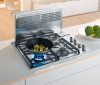
... drawn through and cleaned by the grease filters and then directed outside . Functional description The ventilation system offers two installation options: with the internal DAG 500 exhaust blower (not included) with the DAG 1000 external blower (not included) The air is drawn through and cleaned by the grease filters and then...
... drawn through and cleaned by the grease filters and then directed outside . Functional description The ventilation system offers two installation options: with the internal DAG 500 exhaust blower (not included) with the DAG 1000 external blower (not included) The air is drawn through and cleaned by the grease filters and then...
Operating and Installation manual
Page 9
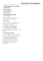
... flash if the temperature of the appliance a On/Off button for the retractable vent and fan b Control panel c Retractable vent d Grease filter e Exhaust blower DAG 500 (not included) The exhaust blower can also be installed behind the appliance.
... flash if the temperature of the appliance a On/Off button for the retractable vent and fan b Control panel c Retractable vent d Grease filter e Exhaust blower DAG 500 (not included) The exhaust blower can also be installed behind the appliance.
Operating and Installation manual
Page 21
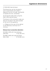
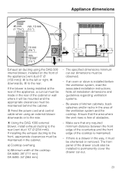
... of the appliance. Must be a minimum of the cabinet or wall. Exhaust duct connection diameters DA 6480, 6490 with internal blower DAG 500 6" C (150 mm) DA 6480, 6490 with external blower DAG 1000 10" C (254 mm) Appliance dimensions 21 a DAG 500 Internal blower The blower box can also be mounted in such a way that the vent...
... of the appliance. Must be a minimum of the cabinet or wall. Exhaust duct connection diameters DA 6480, 6490 with internal blower DAG 500 6" C (150 mm) DA 6480, 6490 with external blower DAG 1000 10" C (254 mm) Appliance dimensions 21 a DAG 500 Internal blower The blower box can also be mounted in such a way that the vent...
Operating and Installation manual
Page 23
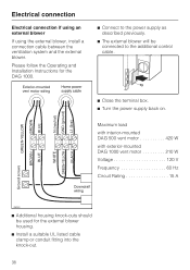
d Feed the power cord and control cable when using the DAG 500 internal blower, installed on the front of the appliance [vent duct 6" C (150 mm)]: a to the left or right, b downwards, c to the rear. e Using the DAG ... oven or stove is a drawer in the cabinet. Be aware of kitchen cabinets, back splashes and/or racks in the rear of the cooktop: DA 6480: 28" (711 mm) DA 6490: 34" (864 mm) - a) Cooktop overhang b) Minimum width of the cabinet or wall where it must be made in the area of the...
d Feed the power cord and control cable when using the DAG 500 internal blower, installed on the front of the appliance [vent duct 6" C (150 mm)]: a to the left or right, b downwards, c to the rear. e Using the DAG ... oven or stove is a drawer in the cabinet. Be aware of kitchen cabinets, back splashes and/or racks in the rear of the cooktop: DA 6480: 28" (711 mm) DA 6490: 34" (864 mm) - a) Cooktop overhang b) Minimum width of the cabinet or wall where it must be made in the area of the...
Operating and Installation manual
Page 24
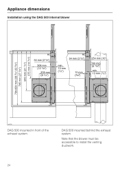
Note that the blower must be accessible to install the venting ductwork. 24 Appliance dimensions Installation using the DAG 500 internal blower DAG 500 mounted in front of the exhaust system. DAG 500 mounted behind the exhaust system.
Note that the blower must be accessible to install the venting ductwork. 24 Appliance dimensions Installation using the DAG 500 internal blower DAG 500 mounted in front of the exhaust system. DAG 500 mounted behind the exhaust system.

Operating and Installation manual
Page 28
... left , right or downwards. ^ Mount the blower box to the housing with 4 screws. 28 Installing the DAG 500 blower box on the venting direction. Decide on the front Venting to mount the DAG 500 blower or DAG 1000 blower adapter. Installation ^ Remove the screws from the ventilation system into the blower motor...
... left , right or downwards. ^ Mount the blower box to the housing with 4 screws. 28 Installing the DAG 500 blower box on the venting direction. Decide on the front Venting to mount the DAG 500 blower or DAG 1000 blower adapter. Installation ^ Remove the screws from the ventilation system into the blower motor...

Operating and Installation manual
Page 29
Venting direction towards the rear: In this case, the DAG 500 blower box must be modified. Installation ^ Remove the small cover on the rear of the ventilation system. ^ Loosen the two screws holding the blower in the box. ^ Take the blower out of the box. ^ Mount the blower on the front of the ventilation system housing using the 2 screws while positioning the vent collar in the opening of the cover. 29
Venting direction towards the rear: In this case, the DAG 500 blower box must be modified. Installation ^ Remove the small cover on the rear of the ventilation system. ^ Loosen the two screws holding the blower in the box. ^ Take the blower out of the box. ^ Mount the blower on the front of the ventilation system housing using the 2 screws while positioning the vent collar in the opening of the cover. 29

Operating and Installation manual
Page 31
Mounting is the same as if installing on the front. ^ Mount the blower on the rear the same way as described for mounting on the rear. Installing the DAG 500 blower box on the rear The blower box can also be installed on the back of the ventilation system: Installation ^ When finished, mount the previously removed cover on the front. ^ Remove the large cover on the front. 31
Mounting is the same as if installing on the front. ^ Mount the blower on the rear the same way as described for mounting on the rear. Installing the DAG 500 blower box on the rear The blower box can also be installed on the back of the ventilation system: Installation ^ When finished, mount the previously removed cover on the front. ^ Remove the large cover on the front. 31
Operating and Installation manual
Page 36
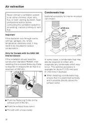
... required. Air extraction Never connect a ventilation system to an existing, inactive chimney or vent flue. where temperature variations exist, it . ^ Fix both with the DAG 500 Internal blower: If the installation should meet the construction standard "R2000", then installing the enclosed Reducing Collar is positioned vertically and if possible directly above...
... required. Air extraction Never connect a ventilation system to an existing, inactive chimney or vent flue. where temperature variations exist, it . ^ Fix both with the DAG 500 Internal blower: If the installation should meet the construction standard "R2000", then installing the enclosed Reducing Collar is positioned vertically and if possible directly above...
Operating and Installation manual
Page 37
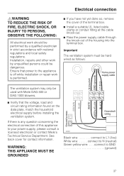
... APPLIANCE MUST BE GROUNDED Black wire connect to your power supply, please consult a licensed electrician or contact Miele's Technical Service Department. Installation, repairs and other work by a qualified electrician in strict accordance with Miele DAG 500 or DAG 1000 blowers. ^ Verify that power to the appliance is off while installation or repair work...
... APPLIANCE MUST BE GROUNDED Black wire connect to your power supply, please consult a licensed electrician or contact Miele's Technical Service Department. Installation, repairs and other work by a qualified electrician in strict accordance with Miele DAG 500 or DAG 1000 blowers. ^ Verify that power to the appliance is off while installation or repair work...
Operating and Installation manual
Page 38
Maximum load with interior-mounted DAG 500 vent motor 420 W with exterior-mounted DAG 1000 vent motor 210 W Voltage 120 V Frequency 60 Hz Circuit Rating 15 A ^ Additional housing knock-outs should be ...
Maximum load with interior-mounted DAG 500 vent motor 420 W with exterior-mounted DAG 1000 vent motor 210 W Voltage 120 V Frequency 60 Hz Circuit Rating 15 A ^ Additional housing knock-outs should be ...
DA6490
Page 1
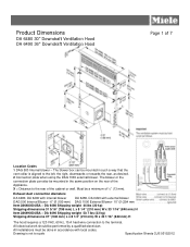
...in such a way that the vent collar is not to the rear of 7 Location Codes 1 DAG 500 Internal blower - Drawing is aligned to the terminal. Must be performed by a qualified electrician. DA 6490 Shipping weight 50.7 lbs (23 kg) Shipping dimensions 37" (940 mm) L x 8 ... DA 6480 Shipping weight 44 lbs (20 kg) Shipping dimensions 31 5/16" (795 mm) L x 8 1/4" (210 mm) W x 33 1/16" (840 mm) H Item 28649050USA - Exhaust duct connection diameters DA 6480, DA 6490 with internal blower DA 6480, DA 6490 with local codes. Product Dimensions DA 6480 30" Downdraft Ventilation Hood DA...
...in such a way that the vent collar is not to the rear of 7 Location Codes 1 DAG 500 Internal blower - Drawing is aligned to the terminal. Must be performed by a qualified electrician. DA 6490 Shipping weight 50.7 lbs (23 kg) Shipping dimensions 37" (940 mm) L x 8 ... DA 6480 Shipping weight 44 lbs (20 kg) Shipping dimensions 31 5/16" (795 mm) L x 8 1/4" (210 mm) W x 33 1/16" (840 mm) H Item 28649050USA - Exhaust duct connection diameters DA 6480, DA 6490 with internal blower DA 6480, DA 6490 with local codes. Product Dimensions DA 6480 30" Downdraft Ventilation Hood DA...
DA6490
Page 2
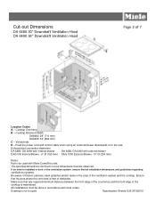
Cooktop Minimum Width DA6480: 28" (711 mm) DA6490: 34" (864 mm) C - Exhaust duct connection diameters DA 6480, DA 6490 with internal blower DA 6480, DA 6490 with external blower DAG 500 Internal Blower - 6" Ø (150 mm) DAG 1000 External Blower- 10" Ø (254 mm) Notes: Not to...racks in accordance with Miele CombiSet units The specified dimensions minimum cut-out dimensions must be done in the area of 7 Location Codes A - All installations must be observed. Vented rear D - Cut-out Dimensions DA 6480 30" Downdraft Ventilation Hood DA 6490 36" Downdraft ...
Cooktop Minimum Width DA6480: 28" (711 mm) DA6490: 34" (864 mm) C - Exhaust duct connection diameters DA 6480, DA 6490 with internal blower DA 6480, DA 6490 with external blower DAG 500 Internal Blower - 6" Ø (150 mm) DAG 1000 External Blower- 10" Ø (254 mm) Notes: Not to...racks in accordance with Miele CombiSet units The specified dimensions minimum cut-out dimensions must be done in the area of 7 Location Codes A - All installations must be observed. Vented rear D - Cut-out Dimensions DA 6480 30" Downdraft Ventilation Hood DA 6490 36" Downdraft ...
DA6490
Page 3
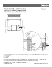
Product and Cut-out Dimensions DA 6480 30" Downdraft Ventilation Hood DA 6490 36" Downdraft Ventilation Hood Page 3 of 7 Exhaust air ducting using the DAG 500 internal blower, installed on the front of the appliance [vent duct 6" ø (150 mm)] A to the left or right B downwards C to scale Specification Sheets OJS ...
Product and Cut-out Dimensions DA 6480 30" Downdraft Ventilation Hood DA 6490 36" Downdraft Ventilation Hood Page 3 of 7 Exhaust air ducting using the DAG 500 internal blower, installed on the front of the appliance [vent duct 6" ø (150 mm)] A to the left or right B downwards C to scale Specification Sheets OJS ...
DA6490
Page 4
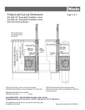
... 5/16" (465 mm) W x 18 1/8" (460 mm) H All installations must be done in front of 7 DAG 500 mounted in accordance with local codes. Product and Cut-out Dimensions DA 6480 30" Downdraft Ventilation Hood DA 6490 36" Downdraft Ventilation Hood DAG 500 Internal Blower Shown with interior mounted DAG 500 vent motor Page 4 of the exhaust system.
... 5/16" (465 mm) W x 18 1/8" (460 mm) H All installations must be done in front of 7 DAG 500 mounted in accordance with local codes. Product and Cut-out Dimensions DA 6480 30" Downdraft Ventilation Hood DA 6490 36" Downdraft Ventilation Hood DAG 500 Internal Blower Shown with interior mounted DAG 500 vent motor Page 4 of the exhaust system.