Operating and Installation manual
Page 2
Contents IMPORTANT SAFETY INSTRUCTIONS 3 Functional description 7 Description of the appliance 8 Operation 10 Raising the vent / Turning on the fan 10 Selecting the power level 10 Delayed shut-off feature ¢15 10 Temperature warning 11 Cleaning and Care 12 Grease filters 13 After Sales Service 15 Installation instructions 17 Caring for the environment 19 Appliance dimensions 20 Installation 26 Installation with the DAG 1000 external blower 34 Air extraction 35 Electrical connection 37 2
Contents IMPORTANT SAFETY INSTRUCTIONS 3 Functional description 7 Description of the appliance 8 Operation 10 Raising the vent / Turning on the fan 10 Selecting the power level 10 Delayed shut-off feature ¢15 10 Temperature warning 11 Cleaning and Care 12 Grease filters 13 After Sales Service 15 Installation instructions 17 Caring for the environment 19 Appliance dimensions 20 Installation 26 Installation with the DAG 1000 external blower 34 Air extraction 35 Electrical connection 37 2
Operating and Installation manual
Page 3
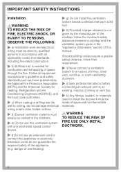
... Instructions carefully before installing or using the Ventilation System. ~ This appliance is any future user. Use the appliance only for outdoor use. ~ This appliance must exist between the appliance and an effective grounding system. on accidentally. If you have questions, contact Miele. ~ b) Before servicing or cleaning the appliance, switch power off at the service panel and lock the service disconnecting means to any doubt, have the electrical...
... Instructions carefully before installing or using the Ventilation System. ~ This appliance is any future user. Use the appliance only for outdoor use. ~ This appliance must exist between the appliance and an effective grounding system. on accidentally. If you have questions, contact Miele. ~ b) Before servicing or cleaning the appliance, switch power off at the service panel and lock the service disconnecting means to any doubt, have the electrical...
Operating and Installation manual
Page 4
... the user and can cause operational faults. ~ g) Before discarding an old appliance, disconnect it from the power supply and remove the power cord. Repairs and other parts of this manual. If in the "Cleaning and care" section of the housing be allowed to prevent appliance damage. Use ,WARNING TO REDUCE THE RISK OF A COOKTOP GREASE FIRE: ~ a) Never leave surface units unattended at a high heat. ~ c) Clean the ventilation system...
... the user and can cause operational faults. ~ g) Before discarding an old appliance, disconnect it from the power supply and remove the power cord. Repairs and other parts of this manual. If in the "Cleaning and care" section of the housing be allowed to prevent appliance damage. Use ,WARNING TO REDUCE THE RISK OF A COOKTOP GREASE FIRE: ~ a) Never leave surface units unattended at a high heat. ~ c) Clean the ventilation system...
Operating and Installation manual
Page 6
... ventilating ductwork. ~ j) Seek professional advice before connecting an exhaust vent to an existing, inactive chimney or vent flue. ~ k) Any fittings, sealant, or materials used to electricity. If local building codes require a greater safety distance, follow the minimum safety distances between a cooktop and the ventilation system given in accordance with any solid-state speed control device. ~ f) Do not use this manual. Extension cords do not damage electrical wiring and/or other hidden utilities. ~ d) Ducted ventilation...
... ventilating ductwork. ~ j) Seek professional advice before connecting an exhaust vent to an existing, inactive chimney or vent flue. ~ k) Any fittings, sealant, or materials used to electricity. If local building codes require a greater safety distance, follow the minimum safety distances between a cooktop and the ventilation system given in accordance with any solid-state speed control device. ~ f) Do not use this manual. Extension cords do not damage electrical wiring and/or other hidden utilities. ~ d) Ducted ventilation...
Operating and Installation manual
Page 9
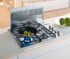
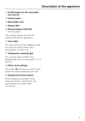
.... 9 h Power level settings The button 0/1 can be reduced to turn off the fan without retracting the vent. g Temperature warning light The warning light will flash if the temperature of the appliance a On/Off button for the retractable vent and fan b Control panel c Retractable vent d Grease filter e Exhaust blower DAG 500 (not included) The exhaust blower can also be used to level 1 and the fan will be installed so that the exhaust vents to either side, downwards, or to the rear. f Vent collar...
.... 9 h Power level settings The button 0/1 can be reduced to turn off the fan without retracting the vent. g Temperature warning light The warning light will flash if the temperature of the appliance a On/Off button for the retractable vent and fan b Control panel c Retractable vent d Grease filter e Exhaust blower DAG 500 (not included) The exhaust blower can also be used to level 1 and the fan will be installed so that the exhaust vents to either side, downwards, or to the rear. f Vent collar...

Operating and Installation manual
Page 14
... a switch at the top. ^ Press the 0/1 button to air dry. ^ While the filters are not in the bottom of the vent. It prevents the ventilation system from the filter casing. ^ Place the filters in place. 14 Use a hot temperature program, e.g. If the retractable vent does not work after the cleaned filters have been replaced: ^ Press the grease filters firmly into the frame at the top, behind the grease filters. Use...
... a switch at the top. ^ Press the 0/1 button to air dry. ^ While the filters are not in the bottom of the vent. It prevents the ventilation system from the filter casing. ^ Place the filters in place. 14 Use a hot temperature program, e.g. If the retractable vent does not work after the cleaned filters have been replaced: ^ Press the grease filters firmly into the frame at the top, behind the grease filters. Use...
Operating and Installation manual
Page 23
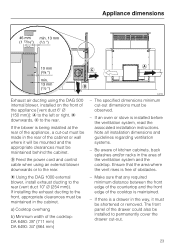
... the ventilation system and the cooktop. e Using the DAG 1000 external blower, install exhaust ducting to permanently cover the drawer cut -out dimensions must be maintained behind the cabinet. Note all installation dimensions and guidelines regarding ventilation systems. - Make sure that the area where the vent rises is being installed at the rear of obstacles. - d Feed the power cord and control cable when using the DAG 500 internal blower, installed on the front of the cooktop: DA 6480: 28...
... the ventilation system and the cooktop. e Using the DAG 1000 external blower, install exhaust ducting to permanently cover the drawer cut -out dimensions must be maintained behind the cabinet. Note all installation dimensions and guidelines regarding ventilation systems. - Make sure that the area where the vent rises is being installed at the rear of obstacles. - d Feed the power cord and control cable when using the DAG 500 internal blower, installed on the front of the cooktop: DA 6480: 28...
Operating and Installation manual
Page 26
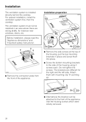
.... ^ Screw the bottom mounting brackets to the front of the housing using 2 screws each. Before installation, please read the "Appliance dimensions" and "Important safety instructions". Use the housing screws which were initially removed. 26 The ventilation system must not be attached to the side of the appliance. Installation The ventilation system is installed directly behind the cooktop. For easiest installation, install the ventilation system first, then the cooktop. The brackets are strong drafts...
.... ^ Screw the bottom mounting brackets to the front of the housing using 2 screws each. Before installation, please read the "Appliance dimensions" and "Important safety instructions". Use the housing screws which were initially removed. 26 The ventilation system must not be attached to the side of the appliance. Installation The ventilation system is installed directly behind the cooktop. For easiest installation, install the ventilation system first, then the cooktop. The brackets are strong drafts...
Operating and Installation manual
Page 33
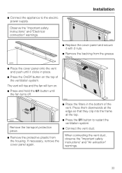
... 0/1 button until the fan turns off. When connecting the vent duct, observe the "Important safety instructions" and "Air extraction" warnings. 33 ^ Connect the appliance to restart the ventilation system. ^ Connect the vent duct. Remove the transport protection piece. ^ Remove the protective plastic from the grease filters. ^ Place the cover panel onto the vent and push until it clicks in the bottom of the ventilation system. Observe the "Important safety instructions" and "Electrical connection" warnings. Installation ^ Replace...
... 0/1 button until the fan turns off. When connecting the vent duct, observe the "Important safety instructions" and "Air extraction" warnings. 33 ^ Connect the appliance to restart the ventilation system. ^ Connect the vent duct. Remove the transport protection piece. ^ Remove the protective plastic from the grease filters. ^ Place the cover panel onto the vent and push until it clicks in the bottom of the ventilation system. Observe the "Important safety instructions" and "Electrical connection" warnings. Installation ^ Replace...
Operating and Installation manual
Page 34
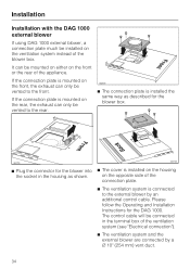
... Operating and Installation Instructions for the blower into the socket in the terminal box of the ventilation system (see "Electrical connection"). ^ The ventilation system and the external blower are connected by an additional control cable. The control cable will be connected in the housing as described for the blower box. ^ Plug the connector for the DAG 1000. If the connection plate is mounted on the rear, the exhaust can only be vented to the rear. ^ The connection plate is installed...
... Operating and Installation Instructions for the blower into the socket in the terminal box of the ventilation system (see "Electrical connection"). ^ The ventilation system and the external blower are connected by an additional control cable. The control cable will be connected in the housing as described for the blower box. ^ Plug the connector for the DAG 1000. If the connection plate is mounted on the rear, the exhaust can only be vented to the rear. ^ The connection plate is installed...

Operating and Installation manual
Page 35
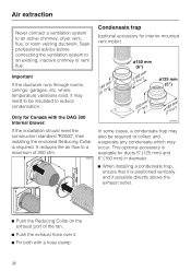
... condensation dripping into spaces within walls or ceilings or in diameter are used. - The ducting should be as short and straight as possible, and the number of sharp bends should be only vented to reduce the risk of the flue. *10" (254 mm) with exterior-mounted vent motor. 35 Follow all local building codes when installing the ventilation system. Gas cooking appliances release carbon monoxide that...
... condensation dripping into spaces within walls or ceilings or in diameter are used. - The ducting should be as short and straight as possible, and the number of sharp bends should be only vented to reduce the risk of the flue. *10" (254 mm) with exterior-mounted vent motor. 35 Follow all local building codes when installing the ventilation system. Gas cooking appliances release carbon monoxide that...
Operating and Installation manual
Page 36
... blower: If the installation should meet the construction standard "R2000", then installing the enclosed Reducing Collar is positioned vertically and if possible directly above the exhaust outlet. ^ Push the Reducing Collar on the exhaust port of 300 cfm. Only for Canada with a hose clamp. 36 This optional accessory is available for interior-mounted vent motor) Important If the ductwork runs through rooms, ceilings...
... blower: If the installation should meet the construction standard "R2000", then installing the enclosed Reducing Collar is positioned vertically and if possible directly above the exhaust outlet. ^ Push the Reducing Collar on the exhaust port of 300 cfm. Only for Canada with a hose clamp. 36 This optional accessory is available for interior-mounted vent motor) Important If the ductwork runs through rooms, ceilings...
Operating and Installation manual
Page 37
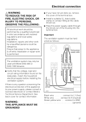
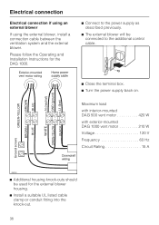
... done so, remove the cover of the terminal box. ^ Install a suitable UL listed cable clamp or conduit fitting at the cable knock-out. ^ Pass the power supply cable through the knock-out of this appliance to L1 (live) White wire: . . . . . See back cover for contact information. connect to GND ground) 37 Installation, repairs and other work by a qualified electrician in strict accordance with Miele DAG 500...
... done so, remove the cover of the terminal box. ^ Install a suitable UL listed cable clamp or conduit fitting at the cable knock-out. ^ Pass the power supply cable through the knock-out of this appliance to L1 (live) White wire: . . . . . See back cover for contact information. connect to GND ground) 37 Installation, repairs and other work by a qualified electrician in strict accordance with Miele DAG 500...
Operating and Installation manual
Page 38
... external blower If using the external blower, install a connection cable between the ventilation system and the external blower. Please follow the Operating and Installation Instructions for the external blower housing. ^ Install a suitable UL listed cable clamp or conduit fitting into the knock-out. 38 Maximum load with interior-mounted DAG 500 vent motor 420 W with exterior-mounted DAG 1000 vent motor 210 W Voltage 120 V Frequency 60 Hz Circuit Rating 15 A ^ Additional housing knock-outs should be connected to the power...
... external blower If using the external blower, install a connection cable between the ventilation system and the external blower. Please follow the Operating and Installation Instructions for the external blower housing. ^ Install a suitable UL listed cable clamp or conduit fitting into the knock-out. 38 Maximum load with interior-mounted DAG 500 vent motor 420 W with exterior-mounted DAG 1000 vent motor 210 W Voltage 120 V Frequency 60 Hz Circuit Rating 15 A ^ Additional housing knock-outs should be connected to the power...
DA6490
Page 1
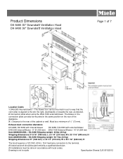
... blower box can also be mounted in the same position on the rear of the cabinet or wall. Drawing is aligned to scale Specification Sheets OJS 05152012 Must be done in such a way that the vent collar is not to the left, the right, downwards or towards the rear, as desired. 2 Connection plate when using the DAG 1000 external blower. Product Dimensions DA 6480 30" Downdraft Ventilation Hood DA 6490 36" Downdraft Ventilation Hood Page...
... blower box can also be mounted in the same position on the rear of the cabinet or wall. Drawing is aligned to scale Specification Sheets OJS 05152012 Must be done in such a way that the vent collar is not to the left, the right, downwards or towards the rear, as desired. 2 Connection plate when using the DAG 1000 external blower. Product Dimensions DA 6480 30" Downdraft Ventilation Hood DA 6490 36" Downdraft Ventilation Hood Page...
DA6490
Page 2
..." Downdraft Ventilation Hood Page 2 of the cooktop is maintained. Exhaust duct connection diameters DA 6480, DA 6490 with internal blower DA 6480, DA 6490 with external blower DAG 500 Internal Blower - 6" Ø (150 mm) DAG 1000 External Blower- 10" Ø (254 mm) Notes: Not to be observed. Cooktop Minimum Width DA6480: 28" (711 mm) DA6490: 34" (864 mm) C - Feed the power cord and control cable when using an external blower downwards or to scale Specification Sheets OJS 05152012 Make sure...
..." Downdraft Ventilation Hood Page 2 of the cooktop is maintained. Exhaust duct connection diameters DA 6480, DA 6490 with internal blower DA 6480, DA 6490 with external blower DAG 500 Internal Blower - 6" Ø (150 mm) DAG 1000 External Blower- 10" Ø (254 mm) Notes: Not to be observed. Cooktop Minimum Width DA6480: 28" (711 mm) DA6490: 34" (864 mm) C - Feed the power cord and control cable when using an external blower downwards or to scale Specification Sheets OJS 05152012 Make sure...
DA6490
Page 3
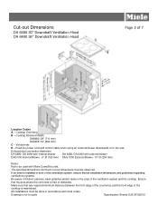
... Cut-out Dimensions DA 6480 30" Downdraft Ventilation Hood DA 6490 36" Downdraft Ventilation Hood Page 3 of 7 Exhaust air ducting using the DAG 500 internal blower, installed on the front of the appliance [vent duct 6" ø (150 mm)] A to the left or right B downwards C to the rear If the blower is not to scale Specification Sheets OJS 05152012 All installations must be done in the rear of the cabinet or wall where it can be mounted and appropriate clearances...
... Cut-out Dimensions DA 6480 30" Downdraft Ventilation Hood DA 6490 36" Downdraft Ventilation Hood Page 3 of 7 Exhaust air ducting using the DAG 500 internal blower, installed on the front of the appliance [vent duct 6" ø (150 mm)] A to the left or right B downwards C to the rear If the blower is not to scale Specification Sheets OJS 05152012 All installations must be done in the rear of the cabinet or wall where it can be mounted and appropriate clearances...
DA6490
Page 4
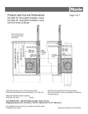
... scale Specification Sheets OJS 05152012 DAG 500 Shipping weight 23 lbs (10.5 kg) Shipping dimensions 24" (610 mm) L x 18 5/16" (465 mm) W x 18 1/8" (460 mm) H All installations must be done in front of 7 DAG 500 mounted in accordance with interior-mounted DAG 500 vent motor 420 W DAG 500 mounted behind the exhaust system. Product and Cut-out Dimensions DA 6480 30" Downdraft Ventilation Hood DA 6490 36" Downdraft Ventilation Hood DAG 500 Internal Blower Shown...
... scale Specification Sheets OJS 05152012 DAG 500 Shipping weight 23 lbs (10.5 kg) Shipping dimensions 24" (610 mm) L x 18 5/16" (465 mm) W x 18 1/8" (460 mm) H All installations must be done in front of 7 DAG 500 mounted in accordance with interior-mounted DAG 500 vent motor 420 W DAG 500 mounted behind the exhaust system. Product and Cut-out Dimensions DA 6480 30" Downdraft Ventilation Hood DA 6490 36" Downdraft Ventilation Hood DAG 500 Internal Blower Shown...
DA6490
Page 5
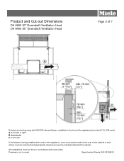
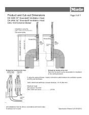
... codes. Drawing is not to the front. Product and Cut-out Dimensions DA 6480 30" Downdraft Ventilation Hood DA 6490 36" Downdraft Ventilation Hood DAG 1000 External Blower Installation using the external blower, install a connection cable between the ventilation system and the external blower. Note that the back must be done in accordance with exterior-mounted DAG 1000 vent motor 210 W All installations must be accessible for installation of the venting ductwork If using the DAG 1000 external blower connection plate Page 5 of 7 Exhaust air ducting to scale Specification Sheets...
... codes. Drawing is not to the front. Product and Cut-out Dimensions DA 6480 30" Downdraft Ventilation Hood DA 6490 36" Downdraft Ventilation Hood DAG 1000 External Blower Installation using the external blower, install a connection cable between the ventilation system and the external blower. Note that the back must be done in accordance with exterior-mounted DAG 1000 vent motor 210 W All installations must be accessible for installation of the venting ductwork If using the DAG 1000 external blower connection plate Page 5 of 7 Exhaust air ducting to scale Specification Sheets...
DA6490
Page 7
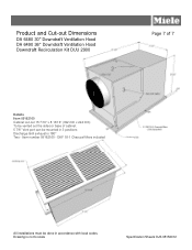
Drawing is 180° Two - Item number 09162160 - Product and Cut-out Dimensions DA 6480 30" Downdraft Ventilation Hood DA 6490 36" Downdraft Ventilation Hood Downdraft Recirculation Kit DUU 2900 2 3 1 Details Item 09162160 Cabinet cut-out 15 7/16" x 8 13/16" (392 mm x 224 mm) To be vented out the sides or base of 7 All installations must be mounted in accordance with local codes. DKF 18-1 Charcoal filters included Page 7 of cabinet. 5 7/8" Vent port can be done in 3 positions Discharge Grill exhaust is not to scale Specification Sheets OJS 05152012
Drawing is 180° Two - Item number 09162160 - Product and Cut-out Dimensions DA 6480 30" Downdraft Ventilation Hood DA 6490 36" Downdraft Ventilation Hood Downdraft Recirculation Kit DUU 2900 2 3 1 Details Item 09162160 Cabinet cut-out 15 7/16" x 8 13/16" (392 mm x 224 mm) To be vented out the sides or base of 7 All installations must be mounted in accordance with local codes. DKF 18-1 Charcoal filters included Page 7 of cabinet. 5 7/8" Vent port can be done in 3 positions Discharge Grill exhaust is not to scale Specification Sheets OJS 05152012


