Service Manual
Page 3
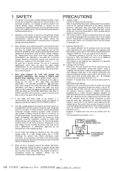
...a substitute replacement which have these special safety characteristics are identified by shading on the schematics and by the manufacturer of the TV screen is recommended that the B1 setting should be identical to each measurement. Don't short between an exposed metal part and... special safety-related characteristics. Electrical components having a return path to assure correct lead dress in the following manner. Some model's power circuit is safe to operate without danger of the cabinet (antenna terminals, video/audio input and output terminals, Control knobs, metal...
...a substitute replacement which have these special safety characteristics are identified by shading on the schematics and by the manufacturer of the TV screen is recommended that the B1 setting should be identical to each measurement. Don't short between an exposed metal part and... special safety-related characteristics. Electrical components having a return path to assure correct lead dress in the following manner. Some model's power circuit is safe to operate without danger of the cabinet (antenna terminals, video/audio input and output terminals, Control knobs, metal...
Service Manual
Page 5
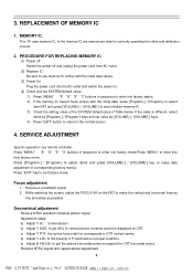
... initialize memory IC. 3) Check the setting value of the SYSTEM default value of vertical picture contents would be displayed on the FBT to CRT horizontal centre. e) Adjust H PHASE, to get 92% of Table below. com. In the memory IC are memorized data for correctly ...Focus adjustment 1. This TV uses memory IC. While watching the screen, adjust the FOCUS VR on CRT. d) Adjust V LIN, to the linearity of corresponding factory menus. Press "EXIT" key to CRT vertical centre. PROCEDURE FOR REPLACING MEMORY IC (1) Power off Switch the power off and unplug the power cord from AC outlet...
... initialize memory IC. 3) Check the setting value of the SYSTEM default value of vertical picture contents would be displayed on the FBT to CRT horizontal centre. e) Adjust H PHASE, to get 92% of Table below. com. In the memory IC are memorized data for correctly ...Focus adjustment 1. This TV uses memory IC. While watching the screen, adjust the FOCUS VR on CRT. d) Adjust V LIN, to the linearity of corresponding factory menus. Press "EXIT" key to CRT vertical centre. PROCEDURE FOR REPLACING MEMORY IC (1) Power off Switch the power off and unplug the power cord from AC outlet...
Service Manual
Page 6
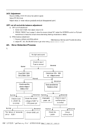
...see if Fuse is normal Abnormal Check D901~D904, C914, IC9601, Q901 Normal Check to see if the collector voltage of Q207 or CPU power pin Check switch power unit Abnormal Check to see if rectifying tube is 13.5V Check to see 110V、180V etc. cn Select RF AGC item.... CRT cut off and white balance adjustment a) CRT cut off adjustment 1. Error Detection Process 1. Receive a Black and White pattern. com. Adjust RC, GC, BC,RD,BD items...
...see if Fuse is normal Abnormal Check D901~D904, C914, IC9601, Q901 Normal Check to see if the collector voltage of Q207 or CPU power pin Check switch power unit Abnormal Check to see if rectifying tube is 13.5V Check to see 110V、180V etc. cn Select RF AGC item.... CRT cut off and white balance adjustment a) CRT cut off adjustment 1. Error Detection Process 1. Receive a Black and White pattern. com. Adjust RC, GC, BC,RD,BD items...
Service Manual
Page 7
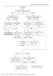
... open Normal Abnormal Video amplifying board is abnormal Inspect the circuit from pin15 of IC201 to Q402 Check the voltage of IC201 2 Check +8V ,+5V power PDF pdf Fact or y Pr o wÿww. com. f i nepr i nt . Maintenance Service and Trouble shooting 2 No raster Normal Whether G2 voltage is normal Abnormal Test...
... open Normal Abnormal Video amplifying board is abnormal Inspect the circuit from pin15 of IC201 to Q402 Check the voltage of IC201 2 Check +8V ,+5V power PDF pdf Fact or y Pr o wÿww. com. f i nepr i nt . Maintenance Service and Trouble shooting 2 No raster Normal Whether G2 voltage is normal Abnormal Test...
Service Manual
Page 8
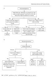
... to see if the deflection yorks are connected, C404 is normal No Check to see if voltage of IC401 and IC401 itself No Inspect +28V power supply 4. f i nepr i nt . Bright line flashes for a moment Yes Check to see if the voltage of pin 11 and pin12 of IC201 is open . Maintenance...
... to see if the deflection yorks are connected, C404 is normal No Check to see if voltage of IC401 and IC401 itself No Inspect +28V power supply 4. f i nepr i nt . Bright line flashes for a moment Yes Check to see if the voltage of pin 11 and pin12 of IC201 is open . Maintenance...
Service Manual
Page 9
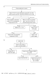
... Inspect the circuit from No.51 of IC201 to see if Yes Inspect C713、C714 No Check to No.3 of IC201 No Inspect +16V power supply 6. f i nepr i nt . com. Maintenance Service and Trouble shooting 5 Picture exists but no sound Make C713/C714 open . cn Touch No.6 OR No.8 of...Yes Inspect IC201 and peripheral component of SK501 4 PDF pdf Fact or y Pr o wÿww. Inspect IC701 and peripheral components of Q702 with No noise Power amplifier is at band RΧ1K. Touch No.6 OR No.8 of IC701 Have noise Make C713 OR C714 collector open . Red probe connect to ground...
... Inspect the circuit from No.51 of IC201 to see if Yes Inspect C713、C714 No Check to No.3 of IC201 No Inspect +16V power supply 6. f i nepr i nt . com. Maintenance Service and Trouble shooting 5 Picture exists but no sound Make C713/C714 open . cn Touch No.6 OR No.8 of...Yes Inspect IC201 and peripheral component of SK501 4 PDF pdf Fact or y Pr o wÿww. Inspect IC701 and peripheral components of Q702 with No noise Power amplifier is at band RΧ1K. Touch No.6 OR No.8 of IC701 Have noise Make C713 OR C714 collector open . Red probe connect to ground...
Service Manual
Page 11
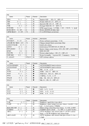
... N Spanish OSD ON = Y;OFF = N Portugal OSD ON = Y;OFF = N DVD signal format,0:CVBS;1:YC;2:YUV;3:hold Power off DVD off delay time Tv to DVD black screen time P7: Items ON DLY T 0 ~ 15 AVS MUTE TIM 0 ~ 255 LOGO COLOR 0 ~ 7 LOGO 0 ~ 1 INT ...AUDIO 0 ~ 1 BTSC 0~1 FAC SW 0 ~ 1 POW MD 0~3 C_10164/5 Preset 6 30 1 0 1 0 0 0 070119 Remark Description Power on black screen time;0-15s...
... N Spanish OSD ON = Y;OFF = N Portugal OSD ON = Y;OFF = N DVD signal format,0:CVBS;1:YC;2:YUV;3:hold Power off DVD off delay time Tv to DVD black screen time P7: Items ON DLY T 0 ~ 15 AVS MUTE TIM 0 ~ 255 LOGO COLOR 0 ~ 7 LOGO 0 ~ 1 INT ...AUDIO 0 ~ 1 BTSC 0~1 FAC SW 0 ~ 1 POW MD 0~3 C_10164/5 Preset 6 30 1 0 1 0 0 0 070119 Remark Description Power on black screen time;0-15s...
Service Manual
Page 12
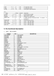
... VIF VIDEO OUT VIF GND PIN 1 2 3 4 5 6 7 8 9 10 11 12 13 14 15 16 17 18 19 20 21 22 23 24 25 26 27 28 29 30 31 32 33 34 35 SP00/14bPWM SP01/PWM SP02/PWM SP03/PWM TEST0 P04.../AD2 P05/AD1 P06/TIM31 SIF auto phase control 8V POWER V RAMP(+) VRAMP CAP SIF auto phase control filter 5V POWER Horizontal SIGNAL OUT FBP IN GND VRAMP AGC Cb IN YcbCr Cr IN YcbCr C-APC...Y SW OUT TEST/EW OUT MCU 5.7 VDD OUT PAL ID FIL 8.7V POWER OUT EXT AU(L)IN/EXT AU2 IN EXT2 IN/C IN YC CHROMA VCC(5.0) EXT 1 IN/YIN YC/YIN Y CbCr 5.7V POWER OUT VIF VIDEO OUT GND 7 DESCRIPTION PDF pdf Fact or y Pr o...
... VIF VIDEO OUT VIF GND PIN 1 2 3 4 5 6 7 8 9 10 11 12 13 14 15 16 17 18 19 20 21 22 23 24 25 26 27 28 29 30 31 32 33 34 35 SP00/14bPWM SP01/PWM SP02/PWM SP03/PWM TEST0 P04.../AD2 P05/AD1 P06/TIM31 SIF auto phase control 8V POWER V RAMP(+) VRAMP CAP SIF auto phase control filter 5V POWER Horizontal SIGNAL OUT FBP IN GND VRAMP AGC Cb IN YcbCr Cr IN YcbCr C-APC...Y SW OUT TEST/EW OUT MCU 5.7 VDD OUT PAL ID FIL 8.7V POWER OUT EXT AU(L)IN/EXT AU2 IN EXT2 IN/C IN YC CHROMA VCC(5.0) EXT 1 IN/YIN YC/YIN Y CbCr 5.7V POWER OUT VIF VIDEO OUT GND 7 DESCRIPTION PDF pdf Fact or y Pr o...
Service Manual
Page 14
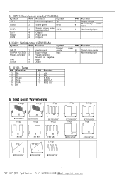
... 95Vpp H R2J10165GC 95Vpp H R2J10165GC 0.9Vpp H R2J10165GC 5Vpp H CRT KR 1Vpp V R2J10165GC H CRT KG 0.8Vpp V R2J10165GC H CRT KB 1.3Vpp R2J10165GC H R2J10165GC H R2J10165GC 9 PDF pdf Fact or... y Pr o www. f i nepr i nt . IC401: Vertical output (STV9302A() Symbol PIN Function INPUT 1 SUPPLY VOLTAGE 2 Flyback generator 3 GND 4 Output 5 Inverting input Supply voltage Flyback generator Ground or negative supply Output Symbol Poutput supply Input 5. IC701: Sound power...
... 95Vpp H R2J10165GC 95Vpp H R2J10165GC 0.9Vpp H R2J10165GC 5Vpp H CRT KR 1Vpp V R2J10165GC H CRT KG 0.8Vpp V R2J10165GC H CRT KB 1.3Vpp R2J10165GC H R2J10165GC H R2J10165GC 9 PDF pdf Fact or... y Pr o www. f i nepr i nt . IC401: Vertical output (STV9302A() Symbol PIN Function INPUT 1 SUPPLY VOLTAGE 2 Flyback generator 3 GND 4 Output 5 Inverting input Supply voltage Flyback generator Ground or negative supply Output Symbol Poutput supply Input 5. IC701: Sound power...
Service Manual
Page 18
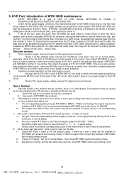
..., while there is signal output from FOSO、TRSO. cn if there is no focus) 1) No light, check the power supply(power supply for pick up then to generate DVD light for data processing, released by MPEG and resolved into video data and audio data, ... it might the problem of servo par(t feeding motor does not work . 1) Check if all the a.m. f i nepr i nt . Under normal power supply conditions, the maintenance plan for MT1389D mono-chip is: first the reset circuit resets the MT1389D, after the crystal oscillator circuit gave the clock...
..., while there is signal output from FOSO、TRSO. cn if there is no focus) 1) No light, check the power supply(power supply for pick up then to generate DVD light for data processing, released by MPEG and resolved into video data and audio data, ... it might the problem of servo par(t feeding motor does not work . 1) Check if all the a.m. f i nepr i nt . Under normal power supply conditions, the maintenance plan for MT1389D mono-chip is: first the reset circuit resets the MT1389D, after the crystal oscillator circuit gave the clock...