Service Manual
Page 1
f i nepr i nt . com. cn SERVICE MANUAL Colour Television Haier model: 21F7A Customer model: MT2025D l FEATURES l DVD-TV 21" COMBO l AUTO TUNE/181 CHANNES l DVD/VCD/SVCD/CD/CD-R/CD-RW/JPEG/MP3 COMPATIBLE l FORMATO DE VIDEO 4:3PS、4:3LB l DOLBY AC-3 DECODE l PANATAL LOCK l ATSC TUNER l AC/DC PDF pdf Fact or y Pr o wÿww. CAUTION READ THIS MANUAL CAREFULLY TO DIAGNOSE TROUBLE CORRECTLY BEFORE OFFERING SERVICE .
f i nepr i nt . com. cn SERVICE MANUAL Colour Television Haier model: 21F7A Customer model: MT2025D l FEATURES l DVD-TV 21" COMBO l AUTO TUNE/181 CHANNES l DVD/VCD/SVCD/CD/CD-R/CD-RW/JPEG/MP3 COMPATIBLE l FORMATO DE VIDEO 4:3PS、4:3LB l DOLBY AC-3 DECODE l PANATAL LOCK l ATSC TUNER l AC/DC PDF pdf Fact or y Pr o wÿww. CAUTION READ THIS MANUAL CAREFULLY TO DIAGNOSE TROUBLE CORRECTLY BEFORE OFFERING SERVICE .
Service Manual
Page 2
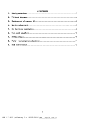
All ICs voltages 10 8. Replacement of memory IC 5 4. ICs functional description 8 6. CONTENTS 1. Purity / convergence adjustment 11 9. . cn Test point waveform 10 7. f i nepr i nt . TV block diagram 4 3. DVD maintenance 13 2 PDF pdf Fact or y Pr o www. com. Safety precautions 3 2. Service adjustment 5 5.
All ICs voltages 10 8. Replacement of memory IC 5 4. ICs functional description 8 6. CONTENTS 1. Purity / convergence adjustment 11 9. . cn Test point waveform 10 7. f i nepr i nt . TV block diagram 4 3. DVD maintenance 13 2 PDF pdf Fact or y Pr o www. com. Safety precautions 3 2. Service adjustment 5 5.
Service Manual
Page 3
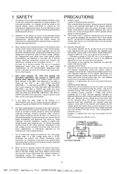
... be checked or adjusted (See ADJUSTMENT OF B1 POWER SUPPLY). 6. The high voltage applied to operate without danger of the cabinet (antenna terminals, video/audio input and output terminals, Control knobs, metal cabinet, screw heads, earphone jack, control shafts, etc.) to be made to the chassis, it forcefully. Discharge the picture tube before attempting meter connection, by visual inspection (incorrect installation, cracked or melted...
... be checked or adjusted (See ADJUSTMENT OF B1 POWER SUPPLY). 6. The high voltage applied to operate without danger of the cabinet (antenna terminals, video/audio input and output terminals, Control knobs, metal cabinet, screw heads, earphone jack, control shafts, etc.) to be made to the chassis, it forcefully. Discharge the picture tube before attempting meter connection, by visual inspection (incorrect installation, cracked or melted...
Service Manual
Page 4
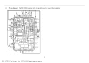
Block diagram R2J10165GC series with stereo intercarrier sound demodulator 4 PDF pdf Fact or y Pr o wÿww. cn com. f i nepr i nt . . 2.
Block diagram R2J10165GC series with stereo intercarrier sound demodulator 4 PDF pdf Fact or y Pr o wÿww. cn com. f i nepr i nt . . 2.
Service Manual
Page 5
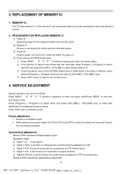
... a crosshatch signal. 2. c) Adjust V POS, the centre horizontal line corresponds to exit factory mode. d) Adjust V LIN, to enter into next factory menu. com. cn 3. Adjustment steps: a) Adjust V SC, S emendation b) Adjust V SIZE, to get the picture horizontal centre correspond to enter into the AC outlet and switch the power on CRT. If the value is in sequence to CRT horizontal centre. f i nepr i nt . This TV uses memory IC. SERVICE ADJUSTMENT Specific operation: use memory...
... a crosshatch signal. 2. c) Adjust V POS, the centre horizontal line corresponds to exit factory mode. d) Adjust V LIN, to enter into next factory menu. com. cn 3. Adjustment steps: a) Adjust V SC, S emendation b) Adjust V SIZE, to get the picture horizontal centre correspond to enter into the AC outlet and switch the power on CRT. If the value is in sequence to CRT horizontal centre. f i nepr i nt . This TV uses memory IC. SERVICE ADJUSTMENT Specific operation: use memory...
Service Manual
Page 6
...) VH colour bar pattern signal. Adjust value, to darkle. A3. com. Select RF AGC item. Receive a Black and White pattern. cn PRESS "MENU" key to page 2, when the screen shows"VK" adjust the SCREEN control on Fly back transformer to make the screen show alternating flashing characters to noise reduce gradually and just disappeared point. No light and sound Normal Check to see...
...) VH colour bar pattern signal. Adjust value, to darkle. A3. com. Select RF AGC item. Receive a Black and White pattern. cn PRESS "MENU" key to page 2, when the screen shows"VK" adjust the SCREEN control on Fly back transformer to make the screen show alternating flashing characters to noise reduce gradually and just disappeared point. No light and sound Normal Check to see...
Service Manual
Page 7
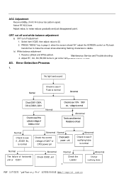
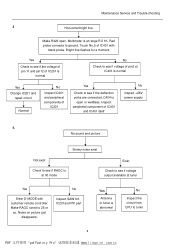
... ,+5V power PDF pdf Fact or y Pr o wÿww. T401, D402 or C419,C420 are broken Q402 is not well welded or open Normal Abnormal Video amplifying board is abnormal Inspect the circuit from pin15 of IC201 to see if be voltage of Q402 is normal Higher Lower InspectT402、R427 etc. com. Maintenance Service and Trouble shooting...
... ,+5V power PDF pdf Fact or y Pr o wÿww. T401, D402 or C419,C420 are broken Q402 is not well welded or open Normal Abnormal Video amplifying board is abnormal Inspect the circuit from pin15 of IC201 to see if be voltage of Q402 is normal Higher Lower InspectT402、R427 etc. com. Maintenance Service and Trouble shooting...
Service Manual
Page 8
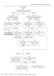
... Yes Change IC201 and repair circuit Normal No Inspect IC201 and peripheral components of IC401 and IC401 itself No Inspect +28V power supply 4. f i nepr i nt . com. cn Inspect peripheral component of IC201 Yes Check to see if voltage output available at tuner Yes Enter D-MODE with black probe. Multimeter is open . Noise on picture just disappears. Maintenance Service and Trouble shooting 3 Horizontal bright line...
... Yes Change IC201 and repair circuit Normal No Inspect IC201 and peripheral components of IC401 and IC401 itself No Inspect +28V power supply 4. f i nepr i nt . com. cn Inspect peripheral component of IC201 Yes Check to see if voltage output available at tuner Yes Enter D-MODE with black probe. Multimeter is open . Noise on picture just disappears. Maintenance Service and Trouble shooting 3 Horizontal bright line...
Service Manual
Page 9
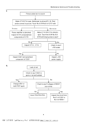
... welded Yes Change V501 or weld V501 again No Check to see if V501 is abnormal. Red probe connect to No.3 of IC701 Have noise Make C713 OR C714 collector open . com. Inspect IC701 and peripheral components of SK501 4 PDF pdf Fact or y Pr o wÿww. Lack of red Check to see...12289;C714 No Check to see if voltages of SK501 are normal No Inspect RI5n0s2p,Re5c0t 3,R504 Yes Inspect the circuit from No.51 of IC201 No Inspect +16V power supply 6. Multimeter is at band RΧ1K. Maintenance Service and Trouble shooting 5 Picture exists but no sound Make C713/C714 open .
... welded Yes Change V501 or weld V501 again No Check to see if V501 is abnormal. Red probe connect to No.3 of IC701 Have noise Make C713 OR C714 collector open . com. Inspect IC701 and peripheral components of SK501 4 PDF pdf Fact or y Pr o wÿww. Lack of red Check to see...12289;C714 No Check to see if voltages of SK501 are normal No Inspect RI5n0s2p,Re5c0t 3,R504 Yes Inspect the circuit from No.51 of IC201 No Inspect +16V power supply 6. Multimeter is at band RΧ1K. Maintenance Service and Trouble shooting 5 Picture exists but no sound Make C713/C714 open .
Service Manual
Page 10
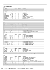
... benchmark voltage adjust YUV benchmark voltage switch YUV benchmark voltage plus P4: Items VIF VCO S TRAP RF AGC VIDEO LVL OK OK 0 ~ 127 0 ~ 7 Preset OK OK 35 7 Remark ◆ ◆ ◆ ◆ Description Picture IF adjust Sound frequency adjust AGC adjust Video demodulation output voltage control P5: Items OSD HP OSD VP H TONE A OSD OSD L TITLE MENU MENU HL 0 ~ 63...
... benchmark voltage adjust YUV benchmark voltage switch YUV benchmark voltage plus P4: Items VIF VCO S TRAP RF AGC VIDEO LVL OK OK 0 ~ 127 0 ~ 7 Preset OK OK 35 7 Remark ◆ ◆ ◆ ◆ Description Picture IF adjust Sound frequency adjust AGC adjust Video demodulation output voltage control P5: Items OSD HP OSD VP H TONE A OSD OSD L TITLE MENU MENU HL 0 ~ 63...
Service Manual
Page 11
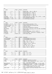
...;OFF = N DVD signal format,0:CVBS;1:YC;2:YUV;3:hold Power off DVD off delay time Tv to DVD black screen time P7: Items ON DLY T 0 ~ 15 AVS MUTE TIM 0 ~ 255 LOGO COLOR 0 ~ 7 LOGO 0 ~ 1 INT AUDIO 0 ~ 1 BTSC 0~1 FAC SW 0 ~ 1 POW MD 0~3 C_10164/5 Preset 6 30 1 0 1 0 0 0 070119 Remark Description Power on black screen time;0-15s Change channal black screen time;10ms Label color choice...
...;OFF = N DVD signal format,0:CVBS;1:YC;2:YUV;3:hold Power off DVD off delay time Tv to DVD black screen time P7: Items ON DLY T 0 ~ 15 AVS MUTE TIM 0 ~ 255 LOGO COLOR 0 ~ 7 LOGO 0 ~ 1 INT AUDIO 0 ~ 1 BTSC 0~1 FAC SW 0 ~ 1 POW MD 0~3 C_10164/5 Preset 6 30 1 0 1 0 0 0 070119 Remark Description Power on black screen time;0-15s Change channal black screen time;10ms Label color choice...
Service Manual
Page 12
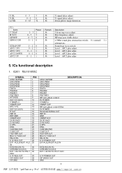
... IN EXT2 IN/C IN YC CHROMA VCC(5.0) EXT 1 IN/YIN YC/YIN Y CbCr 5.7V POWER OUT VIF VIDEO OUT GND 7 DESCRIPTION PDF pdf Fact or y Pr o www. cn ICs functional description 1. U DL V DL LCNR 0 ~ 3 3 № 0~3 0 № 0 ~ 63 32 № U signal delay adjust V signal delay adjust Down pillow shape distortion P11: Items C TRAP H VCO SIF BFP SIF45 G DN...
... IN EXT2 IN/C IN YC CHROMA VCC(5.0) EXT 1 IN/YIN YC/YIN Y CbCr 5.7V POWER OUT VIF VIDEO OUT GND 7 DESCRIPTION PDF pdf Fact or y Pr o www. cn ICs functional description 1. U DL V DL LCNR 0 ~ 3 3 № 0~3 0 № 0 ~ 63 32 № U signal delay adjust V signal delay adjust Down pillow shape distortion P11: Items C TRAP H VCO SIF BFP SIF45 G DN...
Service Manual
Page 14
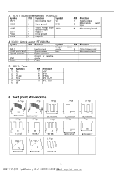
... 1 Non-inverting input 1 Vp SGND 2 Signal ground M/SS SVRR Out 1 PGND OUT2 3 Supply voltage ripple rejection output -INV2 4 Output 1 5 Power ground 6 Output 2 4. U101:Tuner PIN Function 1 Nc 2 Tu 3 Rf agc 4 SCL 5 SDA 6 Btl PIN Function 7 +5V 8 IFA1 9 IF AGC 10 IFD 1OUT 11 IFD 2 OUT PIN Function 7 Supply voltage 8 Mute/standby input switch 9 Non-inverting input 2 PIN stage...
... 1 Non-inverting input 1 Vp SGND 2 Signal ground M/SS SVRR Out 1 PGND OUT2 3 Supply voltage ripple rejection output -INV2 4 Output 1 5 Power ground 6 Output 2 4. U101:Tuner PIN Function 1 Nc 2 Tu 3 Rf agc 4 SCL 5 SDA 6 Btl PIN Function 7 +5V 8 IFA1 9 IF AGC 10 IFD 1OUT 11 IFD 2 OUT PIN Function 7 Supply voltage 8 Mute/standby input switch 9 Non-inverting input 2 PIN stage...
Service Manual
Page 15
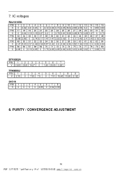
com. PURITY / CONVERGENCE ADJUSTMENT 10 PDF pdf Fact or y Pr o www. cn f i nepr i nt . IC voltages R2J10165G PIN 1 2 3 4 5 6 7 8 9 10 11 12 13 14 15 16 V 0 0.02 4.9 0.03 0 4.72 0.04 0.15 2.05 8.04 2.99 2.36 3.2 5 0.83 0.93 PIN 17 18 19 20 21 22 23 24 25 26 27 28 29 30 31 32 V 0 2.04 1.15...
com. PURITY / CONVERGENCE ADJUSTMENT 10 PDF pdf Fact or y Pr o www. cn f i nepr i nt . IC voltages R2J10165G PIN 1 2 3 4 5 6 7 8 9 10 11 12 13 14 15 16 V 0 0.02 4.9 0.03 0 4.72 0.04 0.15 2.05 8.04 2.99 2.36 3.2 5 0.83 0.93 PIN 17 18 19 20 21 22 23 24 25 26 27 28 29 30 31 32 V 0 2.04 1.15...
Service Manual
Page 16
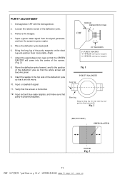
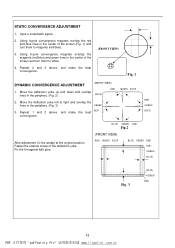
Remove the wedges. 4. Move the deflection yoke backward. 6. Input a crosshatch signal. 11. Fig. 2 (FRONT VIEW) GREEN RASTER CENTER Fig. 3 11 PDF pdf Fact or y Pr o www. Move the deflection yoke forward, and fix the position of the screen. (Fig. 3) 8. Input a green raster signal from the signal generator, and turn the screen to the top side of the deflection yoke so that the GREEN RASTER will come into...
Remove the wedges. 4. Move the deflection yoke backward. 6. Input a crosshatch signal. 11. Fig. 2 (FRONT VIEW) GREEN RASTER CENTER Fig. 3 11 PDF pdf Fact or y Pr o www. Move the deflection yoke forward, and fix the position of the screen. (Fig. 3) 8. Input a green raster signal from the signal generator, and turn the screen to the top side of the deflection yoke so that the GREEN RASTER will come into...
Service Manual
Page 17
... GREEN RED RED GREEN BLUE Fig. 3 BLUE GREEN RED 12 PDF pdf Fact or y Pr o www. cn Repeat 2 and 3 above , and make the best convergence. (FRONT VIEW) Fig. 1 DYNAMIC CONVERGENCE ADJUSTMENT 1. Move the deflection yoke left to white. 4. Repeat 1 and 2 above , and make the best RED convergence. Input a crosshatch signal. 2. Using 6-pole convergence magnets overlap the magenta (red/blue) and green lines in the center of the screen...
... GREEN RED RED GREEN BLUE Fig. 3 BLUE GREEN RED 12 PDF pdf Fact or y Pr o www. cn Repeat 2 and 3 above , and make the best convergence. (FRONT VIEW) Fig. 1 DYNAMIC CONVERGENCE ADJUSTMENT 1. Move the deflection yoke left to white. 4. Repeat 1 and 2 above , and make the best RED convergence. Input a crosshatch signal. 2. Using 6-pole convergence magnets overlap the magenta (red/blue) and green lines in the center of the screen...
Service Manual
Page 18
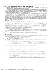
... have problems. 2) Servo part of LSIC for collection, tracing the main shaft to see if there is no pick up action(no light, no OSD display. This problem mainly is caused by MPEG and resolved into video data and audio data, then they are also signals, then check the video output wires and AV filter circuit; Secondly, check motor driver...
... have problems. 2) Servo part of LSIC for collection, tracing the main shaft to see if there is no pick up action(no light, no OSD display. This problem mainly is caused by MPEG and resolved into video data and audio data, then they are also signals, then check the video output wires and AV filter circuit; Secondly, check motor driver...

Service Manual
Page 19
f i nepr i nt . cn com. Sincere Forever Haier Group Haier Industrial Park, No.1, Haier Road 266101, Qingdao, China http://www.haier.com 14 PDF pdf Fact or y Pr o www.
f i nepr i nt . cn com. Sincere Forever Haier Group Haier Industrial Park, No.1, Haier Road 266101, Qingdao, China http://www.haier.com 14 PDF pdf Fact or y Pr o www.

