
User Guide
Page 3
.... However, there is no guarantee that to which the receiver is recommended to Part 15 of the following measures: • Reorient or relocate the receiving antenna. • Increase the separation between the equipment and receiver. • Connect the equipment into an outlet on a circuit different from that interference will not occur...
.... However, there is no guarantee that to which the receiver is recommended to Part 15 of the following measures: • Reorient or relocate the receiving antenna. • Increase the separation between the equipment and receiver. • Connect the equipment into an outlet on a circuit different from that interference will not occur...
User Guide
Page 5
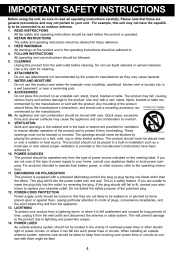
...combination should be taken to keep from overheating. This plug will prevent damage to the product due to . 4. When installing an outside antenna system should not be placed near a swimming pool. 8. RETAIN INSTRUCTIONS The safety and operating instructions should be located in the operating ...can fall , causing serious injury and serious damage to overturn. 9. For example, this product from the wall outlet and disconnect the antenna or cable system. FOLLOW INSTRUCTIONS All operating and use attachments not recommended by items placed upon or against them might be fatal. Use...
...combination should be taken to keep from overheating. This plug will prevent damage to the product due to . 4. When installing an outside antenna system should not be placed near a swimming pool. 8. RETAIN INSTRUCTIONS The safety and operating instructions should be located in the operating ...can fall , causing serious injury and serious damage to overturn. 9. For example, this product from the wall outlet and disconnect the antenna or cable system. FOLLOW INSTRUCTIONS All operating and use attachments not recommended by items placed upon or against them might be fatal. Use...
User Guide
Page 6
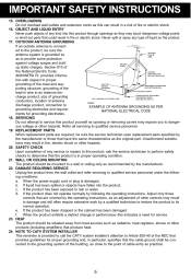
... 19. OBJECT AND LIQUID ENTRY Never push objects of any type of any service or repairs to this product yourself as to an antenna discharge product, size of grounding conductors, location of the NEC that provides guidelines for proper grounding and, in particular, specifies that the... perform safety checks to determine that the cable ground shall be situated away from the wall outlet and refer servicing to EXAMPLE OF ANTENNA GROUNDING AS PER grounding electrodes and requireNATIONAL ELECTRICAL CODE ments for service. 23. e. HEAT The product should be mounted to its normal...
... 19. OBJECT AND LIQUID ENTRY Never push objects of any type of any service or repairs to this product yourself as to an antenna discharge product, size of grounding conductors, location of the NEC that provides guidelines for proper grounding and, in particular, specifies that the... perform safety checks to determine that the cable ground shall be situated away from the wall outlet and refer servicing to EXAMPLE OF ANTENNA GROUNDING AS PER grounding electrodes and requireNATIONAL ELECTRICAL CODE ments for service. 23. e. HEAT The product should be mounted to its normal...
User Guide
Page 7
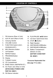
...5 6 7 8 9 10 11 12 13 14 15 16 17 18 19 20 21 22 1. 2. 3. 4. 5. 6. 7. 8. 9. 10. 11. 12. 13. 14. FM Antenna (Rear of Unit) AUX IN Jack (Rear of Unit) Carrying Handle VOLUME Control FUNCTION Switch (AUX.CD/RADIO/OFF) MIX (Random) Button Left Speaker REPEAT Button PROGRAM Button Display TUNING Control... Jack (Rear of Unit) NO. 00002*) (BATTERY COVER PART *Consumer Replaceable Part (See page 17 to order.) 15. PLAY/PAUSE (®p) Button CD Door Open/Close Area STOP (I) Button Right Speaker SKIP/SEARCH n Button SKIP/SEARCH o Button Battery Compartment (Bottom of Unit) (DETACHABLE POWER CORD PART...
...5 6 7 8 9 10 11 12 13 14 15 16 17 18 19 20 21 22 1. 2. 3. 4. 5. 6. 7. 8. 9. 10. 11. 12. 13. 14. FM Antenna (Rear of Unit) AUX IN Jack (Rear of Unit) Carrying Handle VOLUME Control FUNCTION Switch (AUX.CD/RADIO/OFF) MIX (Random) Button Left Speaker REPEAT Button PROGRAM Button Display TUNING Control... Jack (Rear of Unit) NO. 00002*) (BATTERY COVER PART *Consumer Replaceable Part (See page 17 to order.) 15. PLAY/PAUSE (®p) Button CD Door Open/Close Area STOP (I) Button Right Speaker SKIP/SEARCH n Button SKIP/SEARCH o Button Battery Compartment (Bottom of Unit) (DETACHABLE POWER CORD PART...
User Guide
Page 9
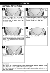
Slide the FUNCTION switch 1 to Radio to turn Stereo ON. ANTENNAS AM-This unit has a built-in ferrite rod antenna, which provides adequate reception in FM broadcasts can be reduced by turning off Stereo. 4 Adjust the VOLUME control as ...FM. 3 FM: Slide the BAND switch to FM ST. If a strong stereo station is for FM reception only. FM-The FM Antenna is broadcasting, the FM Stereo indicator will light. to turn the unit on and select the radio. If reception is selected. Noise ...turn the unit to improve reception. If reception is weak, adjust the length and the angle of the antenna. 8
Slide the FUNCTION switch 1 to Radio to turn Stereo ON. ANTENNAS AM-This unit has a built-in ferrite rod antenna, which provides adequate reception in FM broadcasts can be reduced by turning off Stereo. 4 Adjust the VOLUME control as ...FM. 3 FM: Slide the BAND switch to FM ST. If a strong stereo station is for FM reception only. FM-The FM Antenna is broadcasting, the FM Stereo indicator will light. to turn the unit on and select the radio. If reception is selected. Noise ...turn the unit to improve reception. If reception is weak, adjust the length and the angle of the antenna. 8
User Guide
Page 17
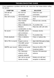
Dirty or defective CD. FM: Telescopic antenna is not on. Close CD Compartment door. Retune the AM or FM broadcast station. Reorient FM telescopic antenna. VOLUME control set to minimum. Power is not properly adjusted. TROUBLESHOOTING GUIDE Try another disc. Slide FUNCTION switch to minimum. Increase volume. CAUSE AC cord ...
Dirty or defective CD. FM: Telescopic antenna is not on. Close CD Compartment door. Retune the AM or FM broadcast station. Reorient FM telescopic antenna. VOLUME control set to minimum. Power is not properly adjusted. TROUBLESHOOTING GUIDE Try another disc. Slide FUNCTION switch to minimum. Increase volume. CAUSE AC cord ...


