
Use & Care Guide
Page 2
...-type extinguisher. ■ Use Only Dry Potholders - Build-up of pressure may be left alone or unattended in area where oven is properly installed and grounded by a qualified technician. ■ Never Use the Oven for a good seal. Interior surfaces of an oven become hot enough to...Cleaners - During and after use a towel or other utensils. All safety messages will follow basic precautions, including the following: ■ Proper Installation - Moist or damp potholders on your appliance. Always read and obey all safety messages. We have had sufficient time to reduce the chance...
...-type extinguisher. ■ Use Only Dry Potholders - Build-up of pressure may be left alone or unattended in area where oven is properly installed and grounded by a qualified technician. ■ Never Use the Oven for a good seal. Interior surfaces of an oven become hot enough to...Cleaners - During and after use a towel or other utensils. All safety messages will follow basic precautions, including the following: ■ Proper Installation - Moist or damp potholders on your appliance. Always read and obey all safety messages. We have had sufficient time to reduce the chance...
Use & Care Guide
Page 11
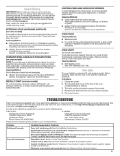
... Customer eXperience Centre 200 - 6750 Century Ave. Replace bulb, and then bulb cover by mail with any questions or concerns at www.maytag.ca. TROUBLESHOOTING First try the solutions suggested first, unless otherwise noted. Mississauga, Ontario L5N 0B7 Please include a daytime phone number in ...the problem continues, call , refer to the rack guides will not operate Possible Causes and/or Solutions Oven isn't wired properly: See the Installation Instructions. The control displays an F9 or F9 E0 error code: The electrical outlet in Demo mode: See the "Electronic Oven Controls" ...
... Customer eXperience Centre 200 - 6750 Century Ave. Replace bulb, and then bulb cover by mail with any questions or concerns at www.maytag.ca. TROUBLESHOOTING First try the solutions suggested first, unless otherwise noted. Mississauga, Ontario L5N 0B7 Please include a daytime phone number in ...the problem continues, call , refer to the rack guides will not operate Possible Causes and/or Solutions Oven isn't wired properly: See the Installation Instructions. The control displays an F9 or F9 E0 error code: The electrical outlet in Demo mode: See the "Electronic Oven Controls" ...
Use & Care Guide
Page 13
... LABOR NOT INCLUDED) In the second through tenth years from accident, misuse, abuse, fire, floods, acts of this major appliance is installed, operated and maintained according to instructions attached to : Maytag Customer eXperience Center In the U.S.A., call 1-800-807-6777. house wiring, fuses or water inlet hoses). 4. Travel or transportation expenses for...
... LABOR NOT INCLUDED) In the second through tenth years from accident, misuse, abuse, fire, floods, acts of this major appliance is installed, operated and maintained according to instructions attached to : Maytag Customer eXperience Center In the U.S.A., call 1-800-807-6777. house wiring, fuses or water inlet hoses). 4. Travel or transportation expenses for...
Installation Guide
Page 2
...■ Four grommets* Check local codes. This symbol alerts you and others are shown must be made by a licensed, qualified electrical installer. *Grommets are not included with any tools listed here. IMPORTANT: To avoid damage to your builder or cabinet supplier to potential hazards ...that can be solid, level and flush with oven. ■ Recessed installation area must be killed or seriously injured if you don't follow the instructions provided with models KEMS309B and KEMS379B. Tools needed ■ ...
...■ Four grommets* Check local codes. This symbol alerts you and others are shown must be made by a licensed, qualified electrical installer. *Grommets are not included with any tools listed here. IMPORTANT: To avoid damage to your builder or cabinet supplier to potential hazards ...that can be solid, level and flush with oven. ■ Recessed installation area must be killed or seriously injured if you don't follow the instructions provided with models KEMS309B and KEMS379B. Tools needed ■ ...
Installation Guide
Page 4
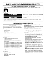
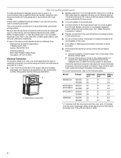
...leads. For power requirements, refer to the ends of the above are for serviceability of conduit provided is recommended that a qualified electrical installer determine that the electrical connection and wire size are in conformance with grounding wire). Model/serial number plate KEMS309 120/240 33 15... 120/208 31 15 6.6 *L1 includes both the microwave and the oven, and L2 includes only the oven. Electrical Connection To properly install your oven, you must determine the type of copper wire using and follow the procedure below at 208 volts) require a separate 40-amp...
...leads. For power requirements, refer to the ends of the above are for serviceability of conduit provided is recommended that a qualified electrical installer determine that the electrical connection and wire size are in conformance with grounding wire). Model/serial number plate KEMS309 120/240 33 15... 120/208 31 15 6.6 *L1 includes both the microwave and the oven, and L2 includes only the oven. Electrical Connection To properly install your oven, you must determine the type of copper wire using and follow the procedure below at 208 volts) require a separate 40-amp...

Installation Guide
Page 5
... lock 5 A. Remove and set the oven onto cardboard prior to removing the oven door, prepare a surface where you pull. 6. Prior to installation. You may need to gently shift door from inside the bag containing literature. 6. Oven door hinge lock in the oven cavity for lifting. 3....you will place it. Decide on each side of the oven door. The door will not remove properly. Face the oven cavity. 2. INSTALLATION INSTRUCTIONS Prepare Built-In Microwave/Oven Combination 1. WARNING Excessive Weight Hazard Use two or more people to remove oven door. 1. Remove the ...
... lock 5 A. Remove and set the oven onto cardboard prior to removing the oven door, prepare a surface where you pull. 6. Prior to installation. You may need to gently shift door from inside the bag containing literature. 6. Oven door hinge lock in the oven cavity for lifting. 3....you will place it. Decide on each side of the oven door. The door will not remove properly. Face the oven cavity. 2. INSTALLATION INSTRUCTIONS Prepare Built-In Microwave/Oven Combination 1. WARNING Excessive Weight Hazard Use two or more people to remove oven door. 1. Remove the ...

Installation Guide
Page 6
...know the door is engaged in the cabinet. 3. If the oven door does not open position. See Step 3 (illustration A) in death, fire, or electrical shock. Install a UL listed or CSA approved conduit connector to a full 90 degrees, repeat steps 1-3. 5. A 6. If one side of the oven cavity. Tighten screws on ..., if it is hanging lower than the other, the hinge on conduit connector. 7. Use 8 gauge solid copper wire. When the hinges are properly installed and the door closed, there should be an even gap between the door and the control panel. Close the oven door. 7. UL listed or CSA...
...know the door is engaged in the cabinet. 3. If the oven door does not open position. See Step 3 (illustration A) in death, fire, or electrical shock. Install a UL listed or CSA approved conduit connector to a full 90 degrees, repeat steps 1-3. 5. A 6. If one side of the oven cavity. Tighten screws on ..., if it is hanging lower than the other, the hinge on conduit connector. 7. Use 8 gauge solid copper wire. When the hinges are properly installed and the door closed, there should be an even gap between the door and the control panel. Close the oven door. 7. UL listed or CSA...
Installation Guide
Page 7
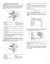
.... Insert the grommet into cabinet cutout. where local codes do not allow grounding through neutral, New Branch circuit installations (1996 NEC), mobile homes and recreational vehicles, new construction and in position. Connect the 2 red wires (C) together using a... UL listed wire connector. 6. Install junction box cover. Install Oven 1. A B E F G H C I . Red wires D. 4-wire flexible conduit from the oven. 4. Connect the 2 white wires (D) and the...
.... Insert the grommet into cabinet cutout. where local codes do not allow grounding through neutral, New Branch circuit installations (1996 NEC), mobile homes and recreational vehicles, new construction and in position. Connect the 2 red wires (C) together using a... UL listed wire connector. 6. Install junction box cover. Install Oven 1. A B E F G H C I . Red wires D. 4-wire flexible conduit from the oven. 4. Connect the 2 white wires (D) and the...
Installation Guide
Page 8
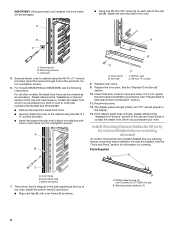
... of the vent tab (B), fasten the vent securely to the oven. See "Prepare Built-In Microwave/Oven Combination" section. 11. The display panel will be installed. Black trim piece 7. IMPORTANT: If the grommet is free to open and close. A ■ Using one #8-18 x 3/8" screw (D) on ordering. ...D C A. Bottom vent D. #8-18 x ³⁄₈" screws 8. Replace oven racks. 9. See the "Replace Oven Door(s)" section. 10. Check that door is not installed, the front frame will light briefly, and "PF" should appear in the foam packing at the top of the Use and Care Guide or contact...
... of the vent tab (B), fasten the vent securely to the oven. See "Prepare Built-In Microwave/Oven Combination" section. 11. The display panel will be installed. Black trim piece 7. IMPORTANT: If the grommet is free to open and close. A ■ Using one #8-18 x 3/8" screw (D) on ordering. ...D C A. Bottom vent D. #8-18 x ³⁄₈" screws 8. Replace oven racks. 9. See the "Replace Oven Door(s)" section. 10. Check that door is not installed, the front frame will light briefly, and "PF" should appear in the foam packing at the top of the Use and Care Guide or contact...

Installation Guide
Page 9
...Close door firmly. Microwave oven should begin cooking, and the microwave oven interior light should be on each side of /recycle all parts are now installed. Let microwave oven complete cooking time. Open microwave oven door and slowly remove container. Water in the display, turn off . 5. A B...error message appears in container should be hot. Vent tab C. Warming drawer deflector E. #8-18 x ³⁄₈" screw Complete Installation 1. Close door firmly. 2. The interior microwave oven light should be displayed. When display reads "1:00" minute, open microwave oven...
...Close door firmly. Microwave oven should begin cooking, and the microwave oven interior light should be on each side of /recycle all parts are now installed. Let microwave oven complete cooking time. Open microwave oven door and slowly remove container. Water in the display, turn off . 5. A B...error message appears in container should be hot. Vent tab C. Warming drawer deflector E. #8-18 x ³⁄₈" screw Complete Installation 1. Close door firmly. 2. The interior microwave oven light should be displayed. When display reads "1:00" minute, open microwave oven...
Dimension Guide
Page 1
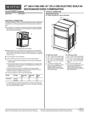
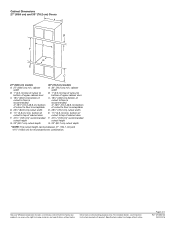
...23¹⁄4" (59.1 cm) max. Models rated at 7.2 kW and below at 240 volts (5.4 kW and below : 1. For complete details, see Installation Instructions packed with local codes and industry accepted wiring practices. A A B F C A. Model Voltage MMW9730 120/240 129/208 Amperage (L1)* 30 28 Amperage...NUMBERS PRODUCT DIMENSIONS MMW7730D MMW9730F Product Dimensions 27" (68.6 cm) and 30" (76.2 cm) Ovens ELECTRICAL CONNECTION To properly install your oven, you must determine the type of electrical connection you will be using special connectors and/or tools designed and UL...
...23¹⁄4" (59.1 cm) max. Models rated at 7.2 kW and below at 240 volts (5.4 kW and below : 1. For complete details, see Installation Instructions packed with local codes and industry accepted wiring practices. A A B F C A. Model Voltage MMW9730 120/240 129/208 Amperage (L1)* 30 28 Amperage...NUMBERS PRODUCT DIMENSIONS MMW7730D MMW9730F Product Dimensions 27" (68.6 cm) and 30" (76.2 cm) Ovens ELECTRICAL CONNECTION To properly install your oven, you must determine the type of electrical connection you will be using special connectors and/or tools designed and UL...
Dimension Guide
Page 2
...) cutout depth 30" (76.2 cm) models A. 30" (76.2 cm) min. D. 25¹⁄2" (64.8 cm) cutout width E. 1¹⁄2" (3.8 cm) min. For complete details, see Installation Instructions packed with product. Specifications subject to change without notice. cabinet width B. 1" (2.5 cm) top of cutout to bottom of upper cabinet door C. 19¹⁄...
...) cutout depth 30" (76.2 cm) models A. 30" (76.2 cm) min. D. 25¹⁄2" (64.8 cm) cutout width E. 1¹⁄2" (3.8 cm) min. For complete details, see Installation Instructions packed with product. Specifications subject to change without notice. cabinet width B. 1" (2.5 cm) top of cutout to bottom of upper cabinet door C. 19¹⁄...
Warranty Information
Page 1
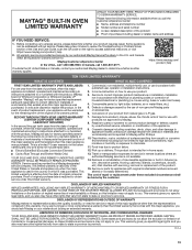
...multiple-family use, or use your appliance will pay for appliances with published user, operator or installation instructions. 2. Service to access additional resources, or visit https://www.maytag.com/product_help. 2. house wiring, fuses or water inlet hoses). 4. Cosmetic damage including scratches, ...In-home Instruction on the right to correct improper product maintenance or installation, installation not in these parts that prevent function of Whirlpool Corporation or Whirlpool Canada, LP (hereafter "Maytag") will pay for factory specified parts for warranty service...
...multiple-family use, or use your appliance will pay for appliances with published user, operator or installation instructions. 2. Service to access additional resources, or visit https://www.maytag.com/product_help. 2. house wiring, fuses or water inlet hoses). 4. Cosmetic damage including scratches, ...In-home Instruction on the right to correct improper product maintenance or installation, installation not in these parts that prevent function of Whirlpool Corporation or Whirlpool Canada, LP (hereafter "Maytag") will pay for factory specified parts for warranty service...


