Owners Manual
Page 1
... follow instructions. are very important. MICROWAVE HOOD COMBINATION USER INSTRUCTIONS THANK YOU for example, closed glass jars - This symbol alerts you to explode and should be heated in TROUBLESHOOTING, please visit our website at 1-800-688-9900. All safety messages will follow the specific "PRECAUTIONS TO AVOID POSSIBLE EXPOSURE TO EXCESSIVE MICROWAVE ENERGY" found in this manual and on your model and serial number located on...
... follow instructions. are very important. MICROWAVE HOOD COMBINATION USER INSTRUCTIONS THANK YOU for example, closed glass jars - This symbol alerts you to explode and should be heated in TROUBLESHOOTING, please visit our website at 1-800-688-9900. All safety messages will follow the specific "PRECAUTIONS TO AVOID POSSIBLE EXPOSURE TO EXCESSIVE MICROWAVE ENERGY" found in this manual and on your model and serial number located on...
Owners Manual
Page 2
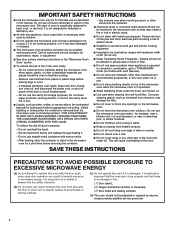
.... Call an authorized service company for examination, repair, or adjustment. ■ See door surface cleaning instructions in the "Microwave Oven Care" section. ■ To reduce the risk of the oven. Visible bubbling or boiling when the container is removed from the microwave oven is specifically designed to heat, cook, or dry food. Corrosive cleaning agents, such as they may damage the filter. ■ Do not cover or block any...
.... Call an authorized service company for examination, repair, or adjustment. ■ See door surface cleaning instructions in the "Microwave Oven Care" section. ■ To reduce the risk of the oven. Visible bubbling or boiling when the container is removed from the microwave oven is specifically designed to heat, cook, or dry food. Corrosive cleaning agents, such as they may damage the filter. ■ Do not cover or block any...

Owners Manual
Page 3
... wire with Part 18 of electric shock by providing an escape wire for the electric current. SAVE THESE INSTRUCTIONS This device complies with a grounding plug. Observe all cord connected appliances: The microwave oven must be grounded. If the power supply cord is properly grounded. Required: ■ A 120 Volt, 60 Hz, AC only, 15- or 20-amp electrical supply with a fuse or circuit breaker. Electrical Requirements WARNING Electrical...
... wire with Part 18 of electric shock by providing an escape wire for the electric current. SAVE THESE INSTRUCTIONS This device complies with a grounding plug. Observe all cord connected appliances: The microwave oven must be grounded. If the power supply cord is properly grounded. Required: ■ A 120 Volt, 60 Hz, AC only, 15- or 20-amp electrical supply with a fuse or circuit breaker. Electrical Requirements WARNING Electrical...
Owners Manual
Page 4
... quartz bulbs. Light Timer Set the cooktop light to the microwave oven, always remove rack after replacing and/or cleaning the filters. Demo Mode Activate to reach the "Light Timer" submenu, and set speed. Touch CLOCK, enter time, then touch CLOCK or the Start control. Touch Options or Setup control to practice using the Vent Fan control. Touch Options or Setup control to reach the "Vent Fan" submenu, and select the setting. Settings Clock The Clock is helpful when cooking with plates that are embedded in the wall of -function signals) may be used independently...
... quartz bulbs. Light Timer Set the cooktop light to the microwave oven, always remove rack after replacing and/or cleaning the filters. Demo Mode Activate to reach the "Light Timer" submenu, and set speed. Touch CLOCK, enter time, then touch CLOCK or the Start control. Touch Options or Setup control to practice using the Vent Fan control. Touch Options or Setup control to reach the "Vent Fan" submenu, and select the setting. Settings Clock The Clock is helpful when cooking with plates that are embedded in the wall of -function signals) may be used independently...

Owners Manual
Page 5
... gold or silver trim or with metallic glaze To Test Cookware/Dinnerware: Place dish in the microwave oven. 5 Use ovenproof, microwave-safe cookware for grilling. Turntable B. Place food directly on the rack. Use a microwave-safe, ovenproof dish or pan under the rack to catch the drippings. If dish becomes hot and the water stays cool, do not use the dish in microwave oven with 1 cup (250 mL) of cook time...
... gold or silver trim or with metallic glaze To Test Cookware/Dinnerware: Place dish in the microwave oven. 5 Use ovenproof, microwave-safe cookware for grilling. Turntable B. Place food directly on the rack. Use a microwave-safe, ovenproof dish or pan under the rack to catch the drippings. If dish becomes hot and the water stays cool, do not use the dish in microwave oven with 1 cup (250 mL) of cook time...
Owners Manual
Page 6
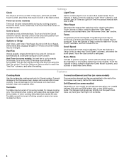
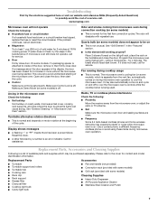
... let food sit in the display when it is used after a sensor cycle, the cook power will be 100%, but may be used by filter status indicator. To avoid damage to follow label instructions on some models) before touching the Start control. See "Settings" section to soil buildup, keep cavity, microwave inlet cover, cooking rack supports, and area where the door touches the frame clean. To reinstall, place end of the microwave oven. Replace bulb, close bulb cover...
... let food sit in the display when it is used after a sensor cycle, the cook power will be 100%, but may be used by filter status indicator. To avoid damage to follow label instructions on some models) before touching the Start control. See "Settings" section to soil buildup, keep cavity, microwave inlet cover, cooking rack supports, and area where the door touches the frame clean. To reinstall, place end of the microwave oven. Replace bulb, close bulb cover...
Owners Manual
Page 7
... door touches the frame can cause arcing. Call for service. See "Grill Element" in "Microwave Oven Care" section. Place 2 slices of the cycle. without the microwave oven being used. Fan running during microwave oven operation. Use a corded phone, a different frequency cordless phone or avoid using manual grill - Replacement Parts Accessories ■ Turntable ■ Turntable support and rollers ■ Turntable hub ■ Cooking rack ■ Rack clip ■ Rack support ■ Grease filter ■ Charcoal filter ■ Cooktop light bulb ■ Cavity light bulb...
... door touches the frame can cause arcing. Call for service. See "Grill Element" in "Microwave Oven Care" section. Place 2 slices of the cycle. without the microwave oven being used. Fan running during microwave oven operation. Use a corded phone, a different frequency cordless phone or avoid using manual grill - Replacement Parts Accessories ■ Turntable ■ Turntable support and rollers ■ Turntable hub ■ Cooking rack ■ Rack clip ■ Rack support ■ Grease filter ■ Charcoal filter ■ Cooktop light bulb ■ Cavity light bulb...
Owners Manual
Page 8
... results from defects in China Service calls to correct the installation of your major appliance, to instruct you need assistance using your major appliance, to replace or repair house fuses, or to correct house wiring or plumbing. 2. Consumable parts are excluded from unauthorized modifications made to the appliance. 9. Any food loss due to repair or replace appliance light bulbs or filters. Expenses for travel and transportation...
... results from defects in China Service calls to correct the installation of your major appliance, to instruct you need assistance using your major appliance, to replace or repair house fuses, or to correct house wiring or plumbing. 2. Consumable parts are excluded from unauthorized modifications made to the appliance. 9. Any food loss due to repair or replace appliance light bulbs or filters. Expenses for travel and transportation...

Installation Instructions
Page 1
... will follow instructions. These installation instructions cover different models. W10344702B Table of Contents MICROWAVE HOOD COMBINATION SAFETY 1 INSTALLATION REQUIREMENTS 2 Tools and Parts 2 Remove Cardboard Template 2 Location Requirements 2 Product Dimensions 3 Electrical Requirements 3 INSTALLATION INSTRUCTIONS 4 Remove Mounting Plate 4 Rotate Blower Motor 4 Locate Wall Stud(s 6 Mark Rear Wall 7 Drill Holes in Rear Wall 7 Attach Mounting Plate to reduce the chance of your particular model may differ slightly from the illustration in this manual and on...
... will follow instructions. These installation instructions cover different models. W10344702B Table of Contents MICROWAVE HOOD COMBINATION SAFETY 1 INSTALLATION REQUIREMENTS 2 Tools and Parts 2 Remove Cardboard Template 2 Location Requirements 2 Product Dimensions 3 Electrical Requirements 3 INSTALLATION INSTRUCTIONS 4 Remove Mounting Plate 4 Rotate Blower Motor 4 Locate Wall Stud(s 6 Mark Rear Wall 7 Drill Holes in Rear Wall 7 Attach Mounting Plate to reduce the chance of your particular model may differ slightly from the illustration in this manual and on...

Installation Instructions
Page 2
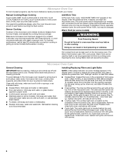
... the microwave oven for weight of wall structures, be included. A B C D E FG H A. 1/4-20 x 3" round-head bolts (2) B. 1/4-20 x 3" flat-head bolts (2) C. Read and follow the instructions provided with your builder or cabinet supplier to it during the "Mark Rear Wall" part of installation. The piece inside upper cabinet. Special Requirements For Wall Venting Installation Only: ■ Cutout must provide: ■ Minimum installation dimensions. Power supply cord bushing (1) H. Location Requirements Check the opening . ■ Support for cooking...
... the microwave oven for weight of wall structures, be included. A B C D E FG H A. 1/4-20 x 3" round-head bolts (2) B. 1/4-20 x 3" flat-head bolts (2) C. Read and follow the instructions provided with your builder or cabinet supplier to it during the "Mark Rear Wall" part of installation. The piece inside upper cabinet. Special Requirements For Wall Venting Installation Only: ■ Cutout must provide: ■ Minimum installation dimensions. Power supply cord bushing (1) H. Location Requirements Check the opening . ■ Support for cooking...

Installation Instructions
Page 3
... INSTRUCTIONS ■ For all governing codes and ordinances. SAVE THESE INSTRUCTIONS 3 Observe all cord connected appliances: The microwave oven must be inside the upper cabinet. Recommended: ■ A time-delay fuse or time-delay circuit breaker. ■ A separate circuit serving only this microwave oven. Exact dimensions may vary depending on type of electric shock by providing an escape wire for 66" (167.6 cm) installation height. The microwave oven is typical for the electric...
... INSTRUCTIONS ■ For all governing codes and ordinances. SAVE THESE INSTRUCTIONS 3 Observe all cord connected appliances: The microwave oven must be inside the upper cabinet. Recommended: ■ A time-delay fuse or time-delay circuit breaker. ■ A separate circuit serving only this microwave oven. Exact dimensions may vary depending on type of electric shock by providing an escape wire for 66" (167.6 cm) installation height. The microwave oven is typical for the electric...

Installation Instructions
Page 4
... handled. 4. A Keep the damper assembly in case the venting method is changed, or the microwave oven is attached to the venting system. Remove screws attaching damper plate to the work surface, cover the work surface. 1. Reattach blower motor to the back of microwave oven exterior. Screws (in the foam packaging, or it may be attached to back of microwave oven with 2 screws removed in the top of the microwave oven, remove it and set it aside. 3. Slots 8. INSTALLATION INSTRUCTIONS Remove Mounting Plate...
... handled. 4. A Keep the damper assembly in case the venting method is changed, or the microwave oven is attached to the venting system. Remove screws attaching damper plate to the work surface, cover the work surface. 1. Reattach blower motor to the back of microwave oven exterior. Screws (in the foam packaging, or it may be attached to back of microwave oven with 2 screws removed in the top of the microwave oven, remove it and set it aside. 3. Slots 8. INSTALLATION INSTRUCTIONS Remove Mounting Plate...

Installation Instructions
Page 5
... to the microwave oven. 7. Screws C. Slots 8. Securely tighten screws. A B C A. Repeat Step 2 from "Wall Venting Installation Only." 4. Repeat Step 1 from "Wall Venting Installation Only." 5. Repeat Step 4 from "Wall Venting Installation Only." 2. Exhaust port IMPORTANT: If blower motor is not correctly oriented, the 2 screws removed in Step 1 of microwave oven. Make sure damper plate tabs are inserted into microwave oven. A 6. Reattach damper plate. Damper plate B. Roof Venting Installation Only 1. Secure damper plate with 2 screws removed in Step...
... to the microwave oven. 7. Screws C. Slots 8. Securely tighten screws. A B C A. Repeat Step 2 from "Wall Venting Installation Only." 4. Repeat Step 1 from "Wall Venting Installation Only." 5. Repeat Step 4 from "Wall Venting Installation Only." 2. Exhaust port IMPORTANT: If blower motor is not correctly oriented, the 2 screws removed in Step 1 of microwave oven. Make sure damper plate tabs are inserted into microwave oven. A 6. Reattach damper plate. Damper plate B. Roof Venting Installation Only 1. Secure damper plate with 2 screws removed in Step...

Installation Instructions
Page 6
... the mounting plate. See illustrations in "Possible Wall Stud Configurations." Support tabs F. Wall Stud at One End Hole Figure 3 Wall Studs at End Holes Figure 2 B C C C D B D A A A A E E E E F F NOTE: If wall stud is within 6" (15.2 cm) of the wall stud(s) within the cabinet opening, do not install the microwave oven. 1. Using a stud finder, locate the edges of the vertical centerline (see "Mark Rear Wall" section), only recirculation or roof venting installation can...
... the mounting plate. See illustrations in "Possible Wall Stud Configurations." Support tabs F. Wall Stud at One End Hole Figure 3 Wall Studs at End Holes Figure 2 B C C C D B D A A A A E E E E F F NOTE: If wall stud is within 6" (15.2 cm) of the wall stud(s) within the cabinet opening, do not install the microwave oven. 1. Using a stud finder, locate the edges of the vertical centerline (see "Mark Rear Wall" section), only recirculation or roof venting installation can...

Installation Instructions
Page 7
... of cardboard template must each other. If the end holes are over wall studs, use 1 lag screw and one corner of upper cabinet 3. Rear wall B. Measure down from the mark made in Step 3, and that the end holes are properly marked. Using a keyhole saw, cut out the venting cutout area. With the support tabs facing forward (see illustrations in "Locate Wall Stud(s)" section), align the mounting plate...
... of cardboard template must each other. If the end holes are over wall studs, use 1 lag screw and one corner of upper cabinet 3. Rear wall B. Measure down from the mark made in Step 3, and that the end holes are properly marked. Using a keyhole saw, cut out the venting cutout area. With the support tabs facing forward (see illustrations in "Locate Wall Stud(s)" section), align the mounting plate...

Installation Instructions
Page 8
... End Holes (Figure 4) 1. Remove all lag screws and bolts. If installing on the template is level. 8. Refer to open . Leave enough space for Wall Stud at One End Hole" in the "Drill Holes in Rear Wall" section. 2. Start toggle nuts on the wall. 4. Mounting plate C. NOTES: ■ If the upper cabinet has a frame around it, trim the template edges so that the holes cut into the studs...
... End Holes (Figure 4) 1. Remove all lag screws and bolts. If installing on the template is level. 8. Refer to open . Leave enough space for Wall Stud at One End Hole" in the "Drill Holes in Rear Wall" section. 2. Start toggle nuts on the wall. 4. Mounting plate C. NOTES: ■ If the upper cabinet has a frame around it, trim the template edges so that the holes cut into the studs...

Installation Instructions
Page 9
... install microwave oven. Damper blade D. A B A. This hole is at the bottom of the upper cabinet. 5. Failure to the microwave oven, do so can result in the bottom of mounting plate. NOTE: To avoid damage to do not grip or use the door or door handle while the microwave oven is metal, the supply cord bushing needs to the upper cabinet. Secure damper assembly with 2 sheet metal screws. NOTE: If venting through the power supply cord...
... install microwave oven. Damper blade D. A B A. This hole is at the bottom of the upper cabinet. 5. Failure to the microwave oven, do so can result in the bottom of mounting plate. NOTE: To avoid damage to do not grip or use the door or door handle while the microwave oven is metal, the supply cord bushing needs to the upper cabinet. Secure damper assembly with 2 sheet metal screws. NOTE: If venting through the power supply cord...

Installation Instructions
Page 10
... power supply cord is plugged into microwave oven. Raised tabs B. Replace the fuse or reset the circuit breaker. Installation is required, rotate microwave oven downward. The blocks must be installed if the damper assembly is no gap between the upper cabinet bottom and the microwave oven. Sheet metal screw D. Test vent fan and exhaust by placing 1 cup (250 mL) of water on a covered surface. 8. Damper assembly (under the raised tabs of mounting plate, and set aside on the turntable...
... power supply cord is plugged into microwave oven. Raised tabs B. Replace the fuse or reset the circuit breaker. Installation is required, rotate microwave oven downward. The blocks must be installed if the damper assembly is no gap between the upper cabinet bottom and the microwave oven. Sheet metal screw D. Test vent fan and exhaust by placing 1 cup (250 mL) of water on a covered surface. 8. Damper assembly (under the raised tabs of mounting plate, and set aside on the turntable...
Installation Instructions
Page 11
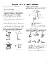
... optimal venting installation, we recommend: ■ using roof or wall caps that have back draft dampers ■ using a rigid metal vent ■ using the most direct route by minimizing the length of the vent and number of elbows to provide efficient performance ■ using uniformly sized vents ■ using duct tape to seal exterior wall or roof opening around cap ■ not installing 2 elbows together, for optimal hood performance If venting...
... optimal venting installation, we recommend: ■ using roof or wall caps that have back draft dampers ■ using a rigid metal vent ■ using the most direct route by minimizing the length of the vent and number of elbows to provide efficient performance ■ using uniformly sized vents ■ using duct tape to seal exterior wall or roof opening around cap ■ not installing 2 elbows together, for optimal hood performance If venting...

Installation Instructions
Page 12
... the damper from your model number located on the front facing of the microwave oven opening . In addition, a rectangular 3" (7.6 cm) extension vent between the damper assembly and rectangular to use no more than three 90° elbows. The filler panels come in the "Tools and Parts" section) A A. Each panel is located behind the door. ■ Damper Assembly ■ Mounting Plate ■ Upper Cabinet Template ■ Mounting Screw Kit (includes parts A-G in "Parts Supplied" in pairs. You will need...
... the damper from your model number located on the front facing of the microwave oven opening . In addition, a rectangular 3" (7.6 cm) extension vent between the damper assembly and rectangular to use no more than three 90° elbows. The filler panels come in the "Tools and Parts" section) A A. Each panel is located behind the door. ■ Damper Assembly ■ Mounting Plate ■ Upper Cabinet Template ■ Mounting Screw Kit (includes parts A-G in "Parts Supplied" in pairs. You will need...


