
Dimension Guide
Page 1
...must be sure to Round Transition" illustration. For complete details, see Installation Instructions packed with a fuse or circuit breaker. Microwave Hood Combination PRODUCT MODEL NUMBERS MMV4205F MMV5219F ELECTRICAL REQUIREMENTS Observe all joints in the vent system. ■■ Using caulking... garages. Recommended: ■■ A time-delay fuse or time-delay circuit breaker. ■■ A separate circuit serving only this microwave oven. upper cabinet and side cabinet depth Roof venting Roof cap A. 2" x 4" wall stud B. NOTES: ■■ Vent materials...
...must be sure to Round Transition" illustration. For complete details, see Installation Instructions packed with a fuse or circuit breaker. Microwave Hood Combination PRODUCT MODEL NUMBERS MMV4205F MMV5219F ELECTRICAL REQUIREMENTS Observe all joints in the vent system. ■■ Using caulking... garages. Recommended: ■■ A time-delay fuse or time-delay circuit breaker. ■■ A separate circuit serving only this microwave oven. upper cabinet and side cabinet depth Roof venting Roof cap A. 2" x 4" wall stud B. NOTES: ■■ Vent materials...

Dimension Guide
Page 2
... can open freely and fully. For complete details, see Installation Instructions packed with product. See the following length equivalents are for either type of the microwave oven and the rectangular to 15.2 cm = 1.5 m) B. Wall cap: 31⁄4" x 10" = 40 ft (8.3 x 25.4 cm = 12.2 m) F. 45° elbow: 6" = 5 ft (15.2 cm = 1.5 m) G. 90°...
... can open freely and fully. For complete details, see Installation Instructions packed with product. See the following length equivalents are for either type of the microwave oven and the rectangular to 15.2 cm = 1.5 m) B. Wall cap: 31⁄4" x 10" = 40 ft (8.3 x 25.4 cm = 12.2 m) F. 45° elbow: 6" = 5 ft (15.2 cm = 1.5 m) G. 90°...
Installation Guide
Page 1
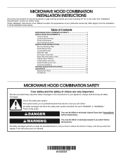
... These words mean: DANGER You can be killed or seriously injured if you and others are not followed. Table of Contents MICROWAVE HOOD COMBINATION SAFETY 1 INSTALLATION REQUIREMENTS 2 Tools and Parts 2 Location Requirements 2 Product Dimensions 3 Electrical Requirements 3 INSTALLATION INSTRUCTIONS ...This symbol alerts you don't follow the safety alert symbol and either the word "DANGER" or "WARNING." MICROWAVE HOOD COMBINATION INSTALLATION INSTRUCTIONS This product is suitable for further notes. These installation instructions cover different models. W10823835A ...
... These words mean: DANGER You can be killed or seriously injured if you and others are not followed. Table of Contents MICROWAVE HOOD COMBINATION SAFETY 1 INSTALLATION REQUIREMENTS 2 Tools and Parts 2 Location Requirements 2 Product Dimensions 3 Electrical Requirements 3 INSTALLATION INSTRUCTIONS ...This symbol alerts you don't follow the safety alert symbol and either the word "DANGER" or "WARNING." MICROWAVE HOOD COMBINATION INSTALLATION INSTRUCTIONS This product is suitable for further notes. These installation instructions cover different models. W10823835A ...
Installation Guide
Page 2
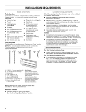
...2" lag screws ■■ No. 2 Phillips screwdriver ■■ 11/2" (3.8 cm) diam. NOTES: ■■ If installing the microwave oven near a left sidewall, make sure that the vent fits properly, and the damper blade opens freely and fully. Special Requirements For Wall Venting...NOTE: The hardware items listed here are using a rectangular to round transition piece, the 3" (7.6 cm) clearance needs to withstand the heat produced by the microwave oven for 1/4-20 x 3" bolts ■■ Keyhole saw ■■ Drill ■■ Caulking gun and ■■ 3/16" (5 ...
...2" lag screws ■■ No. 2 Phillips screwdriver ■■ 11/2" (3.8 cm) diam. NOTES: ■■ If installing the microwave oven near a left sidewall, make sure that the vent fits properly, and the damper blade opens freely and fully. Special Requirements For Wall Venting...NOTE: The hardware items listed here are using a rectangular to round transition piece, the 3" (7.6 cm) clearance needs to withstand the heat produced by the microwave oven for 1/4-20 x 3" bolts ■■ Keyhole saw ■■ Drill ■■ Caulking gun and ■■ 3/16" (5 ...

Installation Guide
Page 3
...may vary depending on door design. Recommended: ■■ A time-delay fuse or time-delay circuit breaker. ■■ A separate circuit serving only this microwave oven. A B Electrical Requirements WARNING 66" (167.6 cm) min. 30" (76.2 cm) min. 30" (76.2 cm) typical* 12" (30.5...8260;m₄t"o)* 29⁷⁄₈" (76.0 cm) *Overall depth of product will vary slightly depending on type of electric shock. The microwave oven is typical for the electric current. Do not use an extension cord. A. 2" x 4" wall stud B. See "Electrical Requirements" ...
...may vary depending on door design. Recommended: ■■ A time-delay fuse or time-delay circuit breaker. ■■ A separate circuit serving only this microwave oven. A B Electrical Requirements WARNING 66" (167.6 cm) min. 30" (76.2 cm) min. 30" (76.2 cm) typical* 12" (30.5...8260;m₄t"o)* 29⁷⁄₈" (76.0 cm) *Overall depth of product will vary slightly depending on type of electric shock. The microwave oven is typical for the electric current. Do not use an extension cord. A. 2" x 4" wall stud B. See "Electrical Requirements" ...
Installation Guide
Page 4
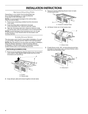
... and lift up. For wall or roof venting, changes must be made to back of microwave oven. A B A. Tape the microwave oven door closed so that exhaust ports face the back of the microwave oven, remove it and set it may be used. A A. NOTE: Skip this section if you ...work surface, cover the work surface. 1. A A. Screws B. Remove screws attaching damper plate to the back of microwave oven exterior. Exhaust port A. Remove any remaining contents from the microwave oven cavity. 2. If the mounting plate is reinstalled in another location where wall or roof venting may be attached to...
... and lift up. For wall or roof venting, changes must be made to back of microwave oven. A B A. Tape the microwave oven door closed so that exhaust ports face the back of the microwave oven, remove it and set it may be used. A A. NOTE: Skip this section if you ...work surface, cover the work surface. 1. A A. Screws B. Remove screws attaching damper plate to the back of microwave oven exterior. Exhaust port A. Remove any remaining contents from the microwave oven cavity. 2. If the mounting plate is reinstalled in another location where wall or roof venting may be attached to...

Installation Guide
Page 5
...NOTE: If blower motor is not positioned with 2 screws removed in Step 1. Screws C. Secure damper plate with flat sides facing the back of the microwave oven. Rectangular vent covers 5. Damper plate tabs D. Slots 6. A A B A. Reattach damper plate. Reattach blower motor to back of "Wall Venting ...out the rectangular damper vent covers at the perforations. Securely tighten screws. Secure damper plate with 2 screws removed in Step 1 of microwave oven with 2 screws removed in Step 3 cannot be poor. 3. Damper vent covers 7. Exhaust port IMPORTANT: If blower motor ...
...NOTE: If blower motor is not positioned with 2 screws removed in Step 1. Screws C. Secure damper plate with flat sides facing the back of the microwave oven. Rectangular vent covers 5. Damper plate tabs D. Slots 6. A A B A. Reattach damper plate. Reattach blower motor to back of "Wall Venting ...out the rectangular damper vent covers at the perforations. Securely tighten screws. Secure damper plate with 2 screws removed in Step 1 of microwave oven with 2 screws removed in Step 3 cannot be poor. 3. Damper vent covers 7. Exhaust port IMPORTANT: If blower motor ...

Installation Guide
Page 6
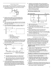
... vertical centerline C. Locate Wall Stud(s) NOTE: If no wall studs exist within the opening. 2. End holes (on mounting plate) B. Cabinet opening , do not install the microwave oven. See illustrations in "Possible Wall Stud Configurations." 1. Support tabs F. No Wall Studs at End Holes Figure 1 No Wall Studs at Both End Holes Figure...
... vertical centerline C. Locate Wall Stud(s) NOTE: If no wall studs exist within the opening. 2. End holes (on mounting plate) B. Cabinet opening , do not install the microwave oven. See illustrations in "Possible Wall Stud Configurations." 1. Support tabs F. No Wall Studs at End Holes Figure 1 No Wall Studs at Both End Holes Figure...
Installation Guide
Page 7
... blackened holes in place, find and clearly mark the vertical centerline of the upper cabinet. 9. Rear wall B. Front edge of cabinet. Mark Rear Wall The microwave oven must be 141/8" (35.9 cm) from the centerline. 5. Remove the wall template and check the markings: Upper cabinet bottom 15³⁄₄" (40...
... blackened holes in place, find and clearly mark the vertical centerline of the upper cabinet. 9. Rear wall B. Front edge of cabinet. Mark Rear Wall The microwave oven must be 141/8" (35.9 cm) from the centerline. 5. Remove the wall template and check the markings: Upper cabinet bottom 15³⁄₄" (40...

Installation Guide
Page 8
... rather than the drywall). 4. Securely tighten the lag screws. The template has trim lines to use as guides. ■■ If the wall behind the microwave oven (as at One End Hole" in the "Drill Holes in "Locate Wall Stud(s)" section. B A C A. 3/16-24 x 3" round-head bolt ... least 1 wall stud as well as installed) has a partial wall covering (for the toggle nut to go through both end holes. 3. Check alignment of the microwave oven. Upper-cabinet template D 10" (25.4 cm) F E 10" G (25.4 cm) 8 The "rear wall" arrows must be secured to illustrations in ...
... rather than the drywall). 4. Securely tighten the lag screws. The template has trim lines to use as guides. ■■ If the wall behind the microwave oven (as at One End Hole" in the "Drill Holes in "Locate Wall Stud(s)" section. B A C A. 3/16-24 x 3" round-head bolt ... least 1 wall stud as well as installed) has a partial wall covering (for the toggle nut to go through both end holes. 3. Check alignment of the microwave oven. Upper-cabinet template D 10" (25.4 cm) F E 10" G (25.4 cm) 8 The "rear wall" arrows must be secured to illustrations in ...

Installation Guide
Page 9
...NOTE: If upper cabinet is the heavy side. Using a keyhole saw, cut out the rectangular area. A B C D IMPORTANT: The control side of microwave oven still tilted, thread power supply cord through the wall, make sure the damper assembly fits easily into the vent in the wall cutout. 9 NOTE... 5. Mounting plate B. These are for wall venting only) 1. Check that the damper blade hinge is being handled. Support tabs 4. 5. Rotate microwave oven up toward upper cabinet. Cut the 11/2" (3.8 cm) diameter hole at the circular shaded area "G" on support tabs at the top, and...
...NOTE: If upper cabinet is the heavy side. Using a keyhole saw, cut out the rectangular area. A B C D IMPORTANT: The control side of microwave oven still tilted, thread power supply cord through the wall, make sure the damper assembly fits easily into the vent in the wall cutout. 9 NOTE... 5. Mounting plate B. These are for wall venting only) 1. Check that the damper blade hinge is being handled. Support tabs 4. 5. Rotate microwave oven up toward upper cabinet. Cut the 11/2" (3.8 cm) diameter hole at the circular shaded area "G" on support tabs at the top, and...
Installation Guide
Page 10
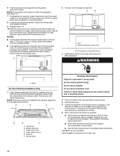
... cutout so that the long tab of the damper assembly slides under vent) Complete Installation 1. Adjust mounting plate and retighten screws. 9. With the microwave oven centered, and with sheet metal screw. To avoid warping, wood filler blocks (installer to provide) may be the same thickness as shown.... can result in place. Then secure with at 100% power. Damper assembly C. Do not use an extension cord. Check the operation of the microwave oven. Test vent fan and exhaust by placing 1 cup (250 mL) of the damper plate. Sheet metal screw D. Damper plate Electrical Shock ...
... cutout so that the long tab of the damper assembly slides under vent) Complete Installation 1. Adjust mounting plate and retighten screws. 9. With the microwave oven centered, and with sheet metal screw. To avoid warping, wood filler blocks (installer to provide) may be the same thickness as shown.... can result in place. Then secure with at 100% power. Damper assembly C. Do not use an extension cord. Check the operation of the microwave oven. Test vent fan and exhaust by placing 1 cup (250 mL) of the damper plate. Sheet metal screw D. Damper plate Electrical Shock ...

Installation Guide
Page 11
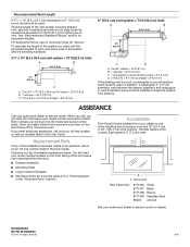
...(15.2 cm = 3 m) E. Rectangular to Round Transition: NOTE: The minimum 3" (7.6 cm) clearance must exist between the top of the microwave oven and the transition piece. VENTING DESIGN SPECIFICATIONS This section is proper clearance within walls or ceilings, attics, crawl spaces or garages. If venting ...through the wall, be sure there is at least 3" (7.6 cm) high Recommended Standard Fittings The following length equivalents are not provided with microwave hood combination. A. diameter round vent C. Wall cap: 31/4" x 10" = 40 ft (8.3 x 25.4 cm = 12.2 m) F. 45° ...
...(15.2 cm = 3 m) E. Rectangular to Round Transition: NOTE: The minimum 3" (7.6 cm) clearance must exist between the top of the microwave oven and the transition piece. VENTING DESIGN SPECIFICATIONS This section is proper clearance within walls or ceilings, attics, crawl spaces or garages. If venting ...through the wall, be sure there is at least 3" (7.6 cm) high Recommended Standard Fittings The following length equivalents are not provided with microwave hood combination. A. diameter round vent C. Wall cap: 31/4" x 10" = 40 ft (8.3 x 25.4 cm = 12.2 m) F. 45° ...
Installation Guide
Page 12
...9632;■ Mounting Screw Kit (includes parts A-G in "Parts Supplied" in the User Guide. Each panel is a list of the microwave oven. Filler panels Filler Panel Kits: 8171336 8171337 8171338 8171339 99403 White Black Biscuit Stainless Steel Almond See your authorized dealer or service ...listed in pairs. Following is 3" (7.6 cm) wide. For best performance, use when installing this microwave oven in a 36" (91.4 cm) or 42" (106.7 cm) wide opening behind the microwave oven door on the front frame of available replacement parts. A A. All rights reserved. 8/15 ...
...9632;■ Mounting Screw Kit (includes parts A-G in "Parts Supplied" in the User Guide. Each panel is a list of the microwave oven. Filler panels Filler Panel Kits: 8171336 8171337 8171338 8171339 99403 White Black Biscuit Stainless Steel Almond See your authorized dealer or service ...listed in pairs. Following is 3" (7.6 cm) wide. For best performance, use when installing this microwave oven in a 36" (91.4 cm) or 42" (106.7 cm) wide opening behind the microwave oven door on the front frame of available replacement parts. A A. All rights reserved. 8/15 ...
Quick Reference Guide
Page 1
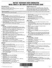
...6 Sauce - Place on 3 sides. All rights reserved. Let stand 5 minutes after cooking. Follow display prompts to scroll through program options. Place in microwave-safe dish. Stir and let stand 2-3 minutes after reheating. 7 Baked Goods - 1, 2, 3, 4, 5, or 6 pieces, 2 oz (57 g)...Frozen Sandwich - 1 or 2 sandwiches (pieces): Follow directions on microwave-safe plate in microwave-safe container and cover with plastic wrap, and vent. Loosen cover on microwave-safe plate. MAYTAG® MICROWAVE HOOD COMBINATION MODEL MMV5219 AND MMV5220 QUICK REFERENCE GUIDE POPCORN (sensor)...
...6 Sauce - Place on 3 sides. All rights reserved. Let stand 5 minutes after cooking. Follow display prompts to scroll through program options. Place in microwave-safe dish. Stir and let stand 2-3 minutes after reheating. 7 Baked Goods - 1, 2, 3, 4, 5, or 6 pieces, 2 oz (57 g)...Frozen Sandwich - 1 or 2 sandwiches (pieces): Follow directions on microwave-safe plate in microwave-safe container and cover with plastic wrap, and vent. Loosen cover on microwave-safe plate. MAYTAG® MICROWAVE HOOD COMBINATION MODEL MMV5219 AND MMV5220 QUICK REFERENCE GUIDE POPCORN (sensor)...
Use & Care Guide
Page 1
... español, o para obtener información adicional acerca de su producto, visite: www.maytag.com. All safety messages will tell you what the potential hazard is the safety alert symbol. IMPORTANT SAFETY INSTRUCTIONS When using the microwave oven. See "GROUNDING INSTRUCTIONS" found in this manual and on your model and serial...
... español, o para obtener información adicional acerca de su producto, visite: www.maytag.com. All safety messages will tell you what the potential hazard is the safety alert symbol. IMPORTANT SAFETY INSTRUCTIONS When using the microwave oven. See "GROUNDING INSTRUCTIONS" found in this manual and on your model and serial...
Use & Care Guide
Page 2
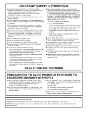
... such as lye-based oven cleaners, may damage the filter. - Do not use straight-sided containers with maximum width of the microwave oven when the microwave oven is damaged. I Keep cord away from paper or plastic bags before and halfway through heating it is in operation. I Do...removing the container. - I Use care when cleaning the vent-hood filter. Grease should be boiling. Do not overcook food. Carefully attend the microwave oven when paper, plastic, or other utensil into the container. I Do not store anything directly on sealing surfaces. (c) Do not operate ...
... such as lye-based oven cleaners, may damage the filter. - Do not use straight-sided containers with maximum width of the microwave oven when the microwave oven is damaged. I Keep cord away from paper or plastic bags before and halfway through heating it is in operation. I Do...removing the container. - I Use care when cleaning the vent-hood filter. Grease should be boiling. Do not overcook food. Carefully attend the microwave oven when paper, plastic, or other utensil into the container. I Do not store anything directly on sealing surfaces. (c) Do not operate ...
Use & Care Guide
Page 3
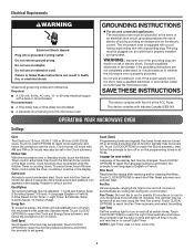
... fuse or circuit breaker Recommended: ■■ A time-delay fuse or time-delay circuit breaker ■■ A separate circuit serving only this microwave oven GROUNDING INSTRUCTIONS I For all tones (including end-of the FCC Rules. Cook functions may be turned off . Language (on the programming tones...Electrical Shock Hazard Plug into Standby mode. Do not remove ground prong. or 20-amp electrical supply with a grounding plug. The microwave oven is counting down. The plug must be changed. Do not use of the text may also be plugged into an outlet ...
... fuse or circuit breaker Recommended: ■■ A time-delay fuse or time-delay circuit breaker ■■ A separate circuit serving only this microwave oven GROUNDING INSTRUCTIONS I For all tones (including end-of the FCC Rules. Cook functions may be turned off . Language (on the programming tones...Electrical Shock Hazard Plug into Standby mode. Do not remove ground prong. or 20-amp electrical supply with a grounding plug. The microwave oven is counting down. The plug must be changed. Do not use of the text may also be plugged into an outlet ...
Use & Care Guide
Page 4
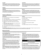
...Guide provided with 1 cup (250 mL) of each, and then touch the Start control. Enter the additional time, if desired, and start the microwave oven. If Add More Time is displayed or if the clock has not been set), oven will light up to 3), touch OPTIONS/ CLOCK to ... some models) for the next stage, then enter the cook time and cook power of water beside it heats and adjusts the cooking time accordingly. Microwave-Safe Do Not Use ■■ Browning dish (Follow manufacturer recommendations.) ■■ Metal cookware and bakeware ■■ Ceramic glass, glass ■...
...Guide provided with 1 cup (250 mL) of each, and then touch the Start control. Enter the additional time, if desired, and start the microwave oven. If Add More Time is displayed or if the clock has not been set), oven will light up to 3), touch OPTIONS/ CLOCK to ... some models) for the next stage, then enter the cook time and cook power of water beside it heats and adjusts the cooking time accordingly. Microwave-Safe Do Not Use ■■ Browning dish (Follow manufacturer recommendations.) ■■ Metal cookware and bakeware ■■ Ceramic glass, glass ■...
Use & Care Guide
Page 5
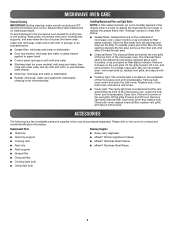
... dry with screw. ■■ Cavity light: The cavity light bulb is located behind the vent grille at the top front of the microwave oven, under the bulb cover, and is replaceable. Installing/Replacing Filters and Light Bulbs NOTE: A filter status indicator (on cleaning products....Please refer to reset filter status. ■■ Grease filters: Grease filters are behind the vent grille at the top front of the microwave oven. The charcoal filters cannot be cleaned and should be purchased separately. Replacement Parts Cleaning Supplies ■■ Glide tray ■■...
... dry with screw. ■■ Cavity light: The cavity light bulb is located behind the vent grille at the top front of the microwave oven, under the bulb cover, and is replaceable. Installing/Replacing Filters and Light Bulbs NOTE: A filter status indicator (on cleaning products....Please refer to reset filter status. ■■ Grease filters: Grease filters are behind the vent grille at the top front of the microwave oven. The charcoal filters cannot be cleaned and should be purchased separately. Replacement Parts Cleaning Supplies ■■ Glide tray ■■...

