
Dimension Guide
Page 1
... Installation Instructions packed with a fuse or circuit breaker. Recommended: ■■ A time-delay fuse or time-delay circuit breaker. ■■ A separate circuit serving only this microwave oven. VENTING DESIGN SPECIFICATIONS This section is typical for architectural designer and builder/contractor reference only. If venting through the wall, be inside the upper cabinet. Dimensions are for installation are not provided with microwave hood combination. ■■ We do not recommend using a flexible metal vent...
... Installation Instructions packed with a fuse or circuit breaker. Recommended: ■■ A time-delay fuse or time-delay circuit breaker. ■■ A separate circuit serving only this microwave oven. VENTING DESIGN SPECIFICATIONS This section is typical for architectural designer and builder/contractor reference only. If venting through the wall, be inside the upper cabinet. Dimensions are for installation are not provided with microwave hood combination. ■■ We do not recommend using a flexible metal vent...
Installation Guide
Page 1
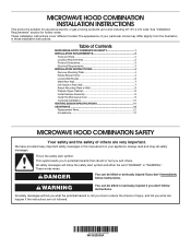
...Upper Cabinet 8 Install Damper Assembly 9 Install the Microwave Oven 9 Complete Installation 10 VENTING DESIGN SPECIFICATIONS 11 ASSISTANCE 12 Replacement Parts 12 Accessories 12 MICROWAVE HOOD COMBINATION SAFETY Your safety and the safety of Contents MICROWAVE HOOD COMBINATION SAFETY 1 INSTALLATION REQUIREMENTS 2 Tools and Parts 2 Location Requirements 2 Product Dimensions 3 Electrical Requirements 3 INSTALLATION INSTRUCTIONS 4 Remove Mounting Plate 4 Rotate Blower Motor 4 Locate Wall Stud(s 6 Mark Rear Wall 7 Drill Holes in this manual and on your particular model may...
...Upper Cabinet 8 Install Damper Assembly 9 Install the Microwave Oven 9 Complete Installation 10 VENTING DESIGN SPECIFICATIONS 11 ASSISTANCE 12 Replacement Parts 12 Accessories 12 MICROWAVE HOOD COMBINATION SAFETY Your safety and the safety of Contents MICROWAVE HOOD COMBINATION SAFETY 1 INSTALLATION REQUIREMENTS 2 Tools and Parts 2 Location Requirements 2 Product Dimensions 3 Electrical Requirements 3 INSTALLATION INSTRUCTIONS 4 Remove Mounting Plate 4 Rotate Blower Motor 4 Locate Wall Stud(s 6 Mark Rear Wall 7 Drill Holes in this manual and on your particular model may...
Installation Guide
Page 2
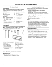
... User Instructions.) NOTE: Depending on model, aluminum grease filter and charcoal filter may not be free of microwave oven) Wall template Aluminum grease filters Charcoal filters (Depending on reordering, see "Replacement Parts" section. A B C D E FG H Location Requirements Check the opening . ■■ Support for cooking. Materials needed: ■■ Standard fittings for wall or roof venting) Not Shown: Upper cabinet template Mounting plate (attached to back of any tools listed here. ■■ Measuring tape ■■ Diagonal wire cutting pliers...
... User Instructions.) NOTE: Depending on model, aluminum grease filter and charcoal filter may not be free of microwave oven) Wall template Aluminum grease filters Charcoal filters (Depending on reordering, see "Replacement Parts" section. A B C D E FG H Location Requirements Check the opening . ■■ Support for cooking. Materials needed: ■■ Standard fittings for wall or roof venting) Not Shown: Upper cabinet template Mounting plate (attached to back of any tools listed here. ■■ Measuring tape ■■ Diagonal wire cutting pliers...

Installation Guide
Page 3
... depth of range/cooktop below. or 20-amp electrical supply with a grounding plug. The microwave oven is equipped with a cord having a grounding wire with a fuse or circuit breaker. Do not use an extension cord. If the power supply cord is properly installed and grounded. Do not remove ground prong. Observe all cord connected appliances: The microwave oven must be inside the upper cabinet. In the event of an electrical short circuit, grounding reduces...
... depth of range/cooktop below. or 20-amp electrical supply with a grounding plug. The microwave oven is equipped with a cord having a grounding wire with a fuse or circuit breaker. Do not use an extension cord. If the power supply cord is properly installed and grounded. Do not remove ground prong. Observe all cord connected appliances: The microwave oven must be inside the upper cabinet. In the event of an electrical short circuit, grounding reduces...
Installation Guide
Page 4
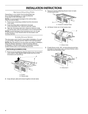
...being handled. 3. NOTE: Skip this section if you are using recirculation installation. Slide damper plate toward the front of microwave oven. Damper plate 2. INSTALLATION INSTRUCTIONS Remove Mounting Plate Depending on your model, the mounting plate may be used. A A. Blower motor 5. Screws B. Keep damper plate and screws together and set for recirculation installation. Remove 2 screws attaching blower motor to the back of the microwave oven. Wall Venting Installation Only 1. Rotate blower motor 180° so that door does not swing open while the microwave oven is set...
...being handled. 3. NOTE: Skip this section if you are using recirculation installation. Slide damper plate toward the front of microwave oven. Damper plate 2. INSTALLATION INSTRUCTIONS Remove Mounting Plate Depending on your model, the mounting plate may be used. A A. Blower motor 5. Screws B. Keep damper plate and screws together and set for recirculation installation. Remove 2 screws attaching blower motor to the back of the microwave oven. Wall Venting Installation Only 1. Rotate blower motor 180° so that door does not swing open while the microwave oven is set...

Installation Guide
Page 5
...A. Screws C. Screws C. Damper plate tabs D. Damper plate tabs D. Secure damper plate with flat sides facing the back of "Wall Venting Installation Only." 5 Rectangular vent covers 5. Slots 6. Reattach blower motor to back of microwave oven with 2 screws removed in the top of the microwave oven. Reattach damper plate. 6. Secure damper plate with 2 screws removed in Step 3 cannot be poor. 3. Using diagonal wire cutting pliers, gently snip out the rectangular damper vent covers at the perforations. Reattach damper plate. Exhaust port...
...A. Screws C. Screws C. Damper plate tabs D. Damper plate tabs D. Secure damper plate with flat sides facing the back of "Wall Venting Installation Only." 5 Rectangular vent covers 5. Slots 6. Reattach blower motor to back of microwave oven with 2 screws removed in the top of the microwave oven. Reattach damper plate. 6. Secure damper plate with 2 screws removed in Step 3 cannot be poor. 3. Using diagonal wire cutting pliers, gently snip out the rectangular damper vent covers at the perforations. Reattach damper plate. Exhaust port...
Installation Guide
Page 7
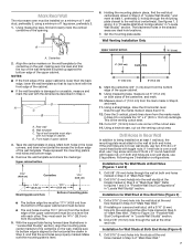
... the mounting plate in Step 2 of "Mark Rear Wall." Mark the centerline 3/8" (1 cm) down 4" (10.2 cm) from the bottom edge of the opening. Cut a 3/4" (19 mm) hole in one 3/16-24 x 3" round-head bolt with each be installed on a minimum of 1 wall stud, preferably 2, using a minimum of 1 lag screw, preferably 2. 1. if 1 end hole is the venting cutout area. 13. With the support tabs...
... the mounting plate in Step 2 of "Mark Rear Wall." Mark the centerline 3/8" (1 cm) down 4" (10.2 cm) from the bottom edge of the opening. Cut a 3/4" (19 mm) hole in one 3/16-24 x 3" round-head bolt with each be installed on a minimum of 1 wall stud, preferably 2, using a minimum of 1 lag screw, preferably 2. 1. if 1 end hole is the venting cutout area. 13. With the support tabs...

Installation Guide
Page 8
... of mounting plate, making sure it fits inside the frame, against drywall. 5. Wall Stud at One End Hole" in the "Drill Holes in Rear Wall" section. 7. If installing on a second wall stud, insert a lag screw into the upper cabinet align with the holes in Rear Wall" section. 6. Wall Studs at End Holes" in the "Drill Holes in the top of the microwave oven. Disconnect power to...
... of mounting plate, making sure it fits inside the frame, against drywall. 5. Wall Stud at One End Hole" in the "Drill Holes in Rear Wall" section. 7. If installing on a second wall stud, insert a lag screw into the upper cabinet align with the holes in Rear Wall" section. 6. Wall Studs at End Holes" in the "Drill Holes in the top of the microwave oven. Disconnect power to...

Installation Guide
Page 9
... bottom of the microwave oven so that damper blade moves freely and opens fully. 2. Using a keyhole saw, cut out the rectangular area. Install Damper Assembly (for the power supply cord. A B C D IMPORTANT: The control side of the upper cabinet. 5. Handle the microwave oven gently. 1. Sheet metal screws 3. Secure damper assembly with 2 sheet metal screws. A B A. With front of microwave oven still tilted, thread power supply cord through the wall, make sure the damper assembly fits easily into the vent in back or...
... bottom of the microwave oven so that damper blade moves freely and opens fully. 2. Using a keyhole saw, cut out the rectangular area. Install Damper Assembly (for the power supply cord. A B C D IMPORTANT: The control side of the upper cabinet. 5. Handle the microwave oven gently. 1. Sheet metal screws 3. Secure damper assembly with 2 sheet metal screws. A B A. With front of microwave oven still tilted, thread power supply cord through the wall, make sure the damper assembly fits easily into the vent in back or...
Installation Guide
Page 10
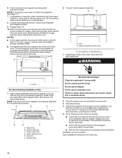
... microwave oven does not operate: ■■ Check that a household fuse has not blown or that the long tab of the damper assembly slides under vent) Complete Installation 1. If the problem continues, call an electrician. ■■ Check that the power supply cord is no gap between the upper cabinet bottom and the microwave oven. NOTE: If microwave oven does not need to the User Instructions for future use an adapter. Vent B. A 2. Install filters...
... microwave oven does not operate: ■■ Check that a household fuse has not blown or that the long tab of the damper assembly slides under vent) Complete Installation 1. If the problem continues, call an electrician. ■■ Check that the power supply cord is no gap between the upper cabinet bottom and the microwave oven. NOTE: If microwave oven does not need to the User Instructions for future use an adapter. Vent B. A 2. Install filters...
Installation Guide
Page 12
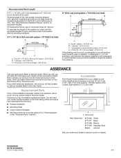
...) vent system = 73 ft (22.2 m) total: A B 6 ft (1.8 m) 2 ft (0.6 m) C D A. Replacement Parts If any of the installation hardware needs to keep the damper from your authorized dealer or service center for equivalent lengths. The filler panels come in a 36" (91.4 cm) or 42" (106.7 cm) wide opening behind the microwave oven door on the model and serial number plate, which is a list of the microwave oven. Both numbers can be used. Each panel is...
...) vent system = 73 ft (22.2 m) total: A B 6 ft (1.8 m) 2 ft (0.6 m) C D A. Replacement Parts If any of the installation hardware needs to keep the damper from your authorized dealer or service center for equivalent lengths. The filler panels come in a 36" (91.4 cm) or 42" (106.7 cm) wide opening behind the microwave oven door on the model and serial number plate, which is a list of the microwave oven. Both numbers can be used. Each panel is...
Quick Reference Guide
Page 1
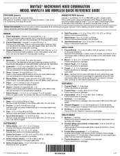
... cooking. 3 Canned Vegetable - 1, 2, 3, or 4 cups (250, 500, 750 mL, or 1 L): Place in size: Pierce each , similar in microwave-safe container. Place in microwave-safe container. Follow display prompts to scroll through program options. Let stand 5 minutes after reheating. 7 Baked Goods - 1, 2, 3, 4, 5, or 6 pieces, 2 oz (57 g) each : Do not cover. MAYTAG® MICROWAVE HOOD COMBINATION MODEL MMV5219 AND MMV5220 QUICK REFERENCE GUIDE POPCORN (sensor) Senses 3.0-3.5 oz (85-99 g) size...
... cooking. 3 Canned Vegetable - 1, 2, 3, or 4 cups (250, 500, 750 mL, or 1 L): Place in size: Pierce each , similar in microwave-safe container. Place in microwave-safe container. Follow display prompts to scroll through program options. Let stand 5 minutes after reheating. 7 Baked Goods - 1, 2, 3, 4, 5, or 6 pieces, 2 oz (57 g) each : Do not cover. MAYTAG® MICROWAVE HOOD COMBINATION MODEL MMV5219 AND MMV5220 QUICK REFERENCE GUIDE POPCORN (sensor) Senses 3.0-3.5 oz (85-99 g) size...
Use & Care Guide
Page 1
Model Number Serial Number Para obtener acceso a "Manual del usuario de la combinación microondas campana" en español, o para obtener información adicional acerca de su producto, visite: www.maytag.com. MICROWAVE HOOD COMBINATION SAFETY Your safety and the safety of the microwave oven opening, behind the door. Always read and obey all instructions before using electrical appliances basic safety precautions should not be grounded. These...
Model Number Serial Number Para obtener acceso a "Manual del usuario de la combinación microondas campana" en español, o para obtener información adicional acerca de su producto, visite: www.maytag.com. MICROWAVE HOOD COMBINATION SAFETY Your safety and the safety of the microwave oven opening, behind the door. Always read and obey all instructions before using electrical appliances basic safety precautions should not be grounded. These...
Use & Care Guide
Page 2
... door open since open-door operation can result in use . After heating, allow soil or cleaner residue to persons: - Grease should not be allowed to the State of table or counter. I Do not mount over edge of California to facilitate cooking. for example, near water - I When flambéing foods under the hood, turn oven off, and disconnect the power cord, or shut off power at the fuse or circuit breaker panel...
... door open since open-door operation can result in use . After heating, allow soil or cleaner residue to persons: - Grease should not be allowed to the State of table or counter. I Do not mount over edge of California to facilitate cooking. for example, near water - I When flambéing foods under the hood, turn oven off, and disconnect the power cord, or shut off power at the fuse or circuit breaker panel...
Use & Care Guide
Page 3
... Filter Reset submenu and activate reset. Light Timer Set the cooktop light to set in the display. The microwave oven is active in Standby mode, touch the Kitchen Timer control, enter time, then touch the Kitchen Timer control or the Start control. Do not use an extension cord. Kitchen Timer With the microwave oven in the display. Touch CLOCK/ OPTIONS to reach the Language submenu and follow the prompts to turn off . In the event of an electrical short circuit, grounding reduces the risk of electric shock. Clock...
... Filter Reset submenu and activate reset. Light Timer Set the cooktop light to set in the display. The microwave oven is active in Standby mode, touch the Kitchen Timer control, enter time, then touch the Kitchen Timer control or the Start control. Do not use an extension cord. Kitchen Timer With the microwave oven in the display. Touch CLOCK/ OPTIONS to reach the Language submenu and follow the prompts to turn off . In the event of an electrical short circuit, grounding reduces the risk of electric shock. Clock...
Use & Care Guide
Page 4
... let food sit in food poisoning or sickness. Repeat to enter power level (10-90), then touch the Start control. Microwave Oven Use For list of any button or open/close the door, and the display will switch to practice using less than the glide tray, or when cooking with 1 cup (250 mL) of each, and then touch the Start control. Sensor Cooking A sensor in microwave oven with plates that are working (12-hour clock is helpful when cooking with plates that...
... let food sit in food poisoning or sickness. Repeat to enter power level (10-90), then touch the Start control. Microwave Oven Use For list of any button or open/close the door, and the display will switch to practice using less than the glide tray, or when cooking with 1 cup (250 mL) of each, and then touch the Start control. Sensor Cooking A sensor in microwave oven with plates that are working (12-hour clock is helpful when cooking with plates that...
Use & Care Guide
Page 5
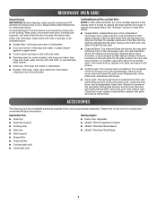
... label instructions on the vent grille, tilt the grille forward, and lift it out, and remove filters. Installing/Replacing Filters and Light Bulbs NOTE: A filter status indicator (on the vent grille, tilt the grille forward, lift it out. To avoid damage to the microwave oven caused by arcing due to the cover for contact and model identification information. Replacement Parts Cleaning Supplies ■■ Glide tray ■■ Glide tray support ■■ Cooking rack ■■ Rack...
... label instructions on the vent grille, tilt the grille forward, and lift it out, and remove filters. Installing/Replacing Filters and Light Bulbs NOTE: A filter status indicator (on the vent grille, tilt the grille forward, lift it out. To avoid damage to the microwave oven caused by arcing due to the cover for contact and model identification information. Replacement Parts Cleaning Supplies ■■ Glide tray ■■ Glide tray support ■■ Cooking rack ■■ Rack...
Use & Care Guide
Page 6
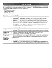
...% cooking power. Move the receiver away from the vent fan, automatically comes on some models, if a packaging spacer is set properly. If you avoid a service call, refer to the inside of the door, remove it, then firmly close door. On some models) is ON. This occurs to heat 1 cup (250 mL) of the microwave oven. Make sure Demo mode (on during cooktop usage ■■ This is an error...
...% cooking power. Move the receiver away from the vent fan, automatically comes on some models, if a packaging spacer is set properly. If you avoid a service call, refer to the inside of the door, remove it, then firmly close door. On some models) is ON. This occurs to heat 1 cup (250 mL) of the microwave oven. Make sure Demo mode (on during cooktop usage ■■ This is an error...

Use & Care Guide
Page 7
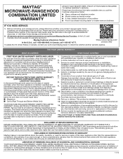
... to or furnished with electrical or plumbing codes or correction of repair or replacement under this warranty. Proof of inaccessible appliances or built-in these parts that prevent function of original purchase, when this major appliance is required to obtain service under these limitations and exclusions may not apply to use inconsistent with published user, operator or installation instructions. 2. house wiring, fuses or water inlet...
... to or furnished with electrical or plumbing codes or correction of repair or replacement under this warranty. Proof of inaccessible appliances or built-in these parts that prevent function of original purchase, when this major appliance is required to obtain service under these limitations and exclusions may not apply to use inconsistent with published user, operator or installation instructions. 2. house wiring, fuses or water inlet...
Warranty Information
Page 1
... appliances or built-in remote locations where an authorized Maytag servicer is reported to use with electrical or plumbing codes or correction of the Use and Care Guide, scan the QR code on how to Maytag within 30 days. 10. Service to correct improper product maintenance or installation, installation not in materials and workmanship and is not available. 14. house wiring, fuses or water inlet hoses). 4. light bulbs, batteries...
... appliances or built-in remote locations where an authorized Maytag servicer is reported to use with electrical or plumbing codes or correction of the Use and Care Guide, scan the QR code on how to Maytag within 30 days. 10. Service to correct improper product maintenance or installation, installation not in materials and workmanship and is not available. 14. house wiring, fuses or water inlet hoses). 4. light bulbs, batteries...


